Monthly Archives: May 2016

Through the Keyhole and Into the Shire

doorsofdurin

Historically, one of the oldest references to a magical wand describes the supernatural item in the form of a staff. Staffs, if not too ornate, provide their owners with a lethal weapon that many observers would regard as an ordinary walking stick. For my final project, I have assembled a moonlight illuminating staff with the power to unlock a door. This idea of unlocking doors with moonlight stemmed in part from the wondrously entertaining, magical adventure novel, The Hobbit by Tolkien. In the story, the protagonists are given the following clue to enter the Lonely Mountain and reclaim their treasure from the treacherous dragon, Smaug: “’Stand by the grey stone when the thrush knocks’, read Elrond, ‘and the setting sun with the last light of Durin’s Day will shine upon the key-hole.’” The last light actually alludes to the setting sun in the book; the movie embellishes the riddle by declaring moonlight alone to be the last light of Durin’s Day.

durins_day_thMoonlight does, however, play a vital role in the novel, as Durin’s Day is, “when the last moon of Autumn and the sun are in the sky together.”
The technique chosen for developing a light source mimicking moonlight was to wire a multitude of colored LEDs together such that the number of each color was proportional to the relative intensity at that particular wavelength in the spectrum for moonlight. With only a finite number of different colors of LEDs in the circuit, the light source would serve as an approximation of moonlight. However, by inserting a sufficiently high number of LEDs into the circuit and extending the variety of colors fairly evenly across the visible region of the spectrum, this approximation should be sufficient. The spectrum that I used to determine the number of each color, originally from a paper by Ciocca & Wang, can be viewed at the following link:

http://physics.stackexchange.com/questions/244922/why-does-moonlight-have-a-lower-color-temperature

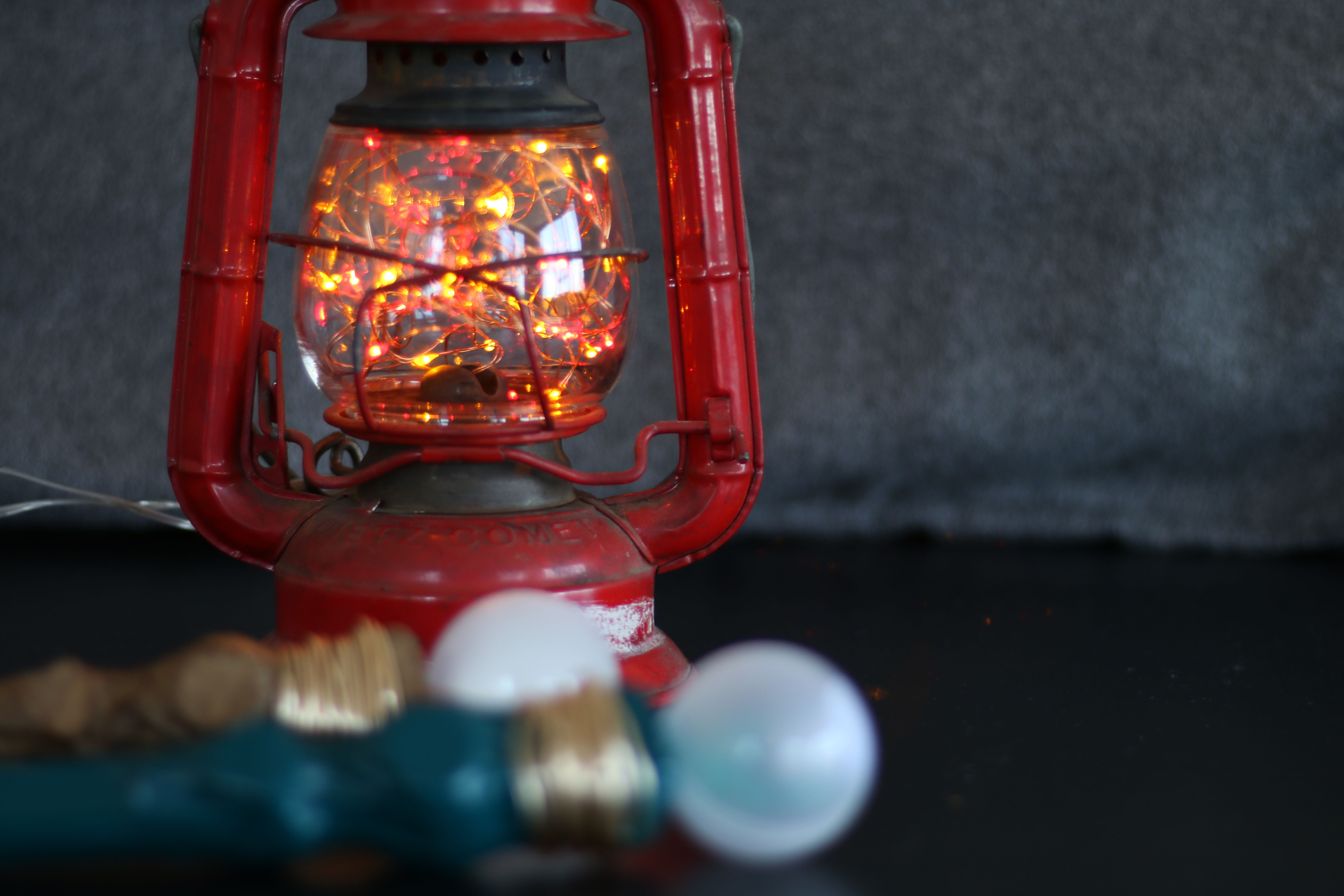
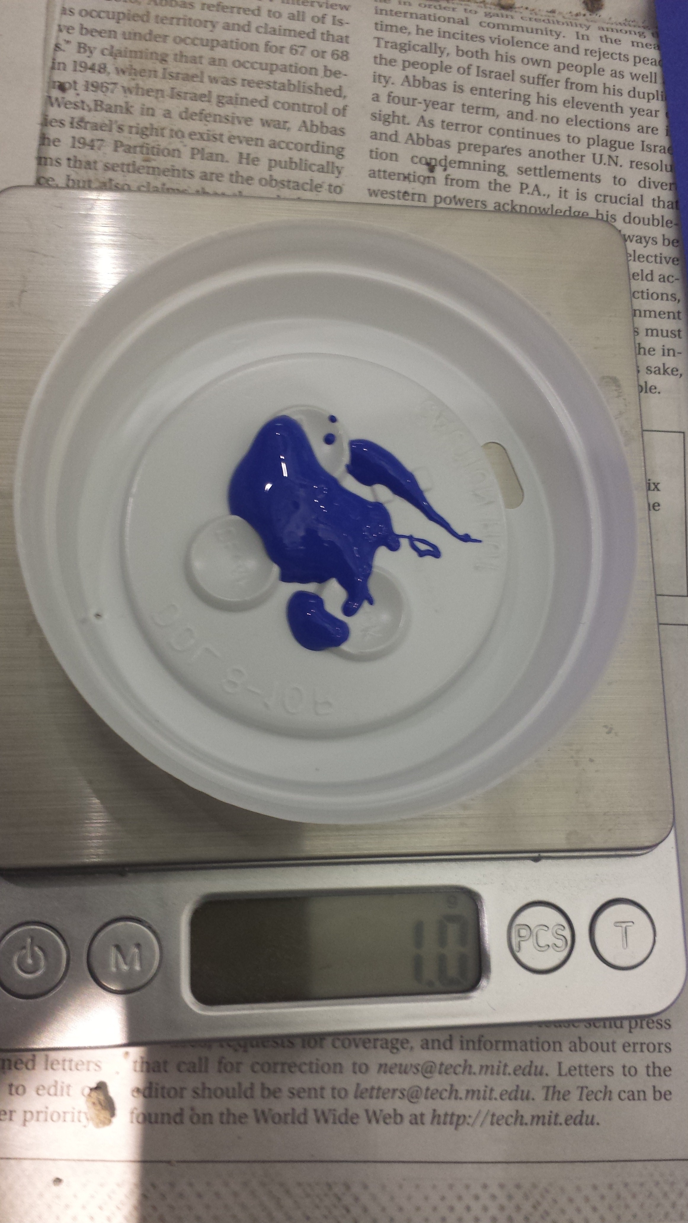
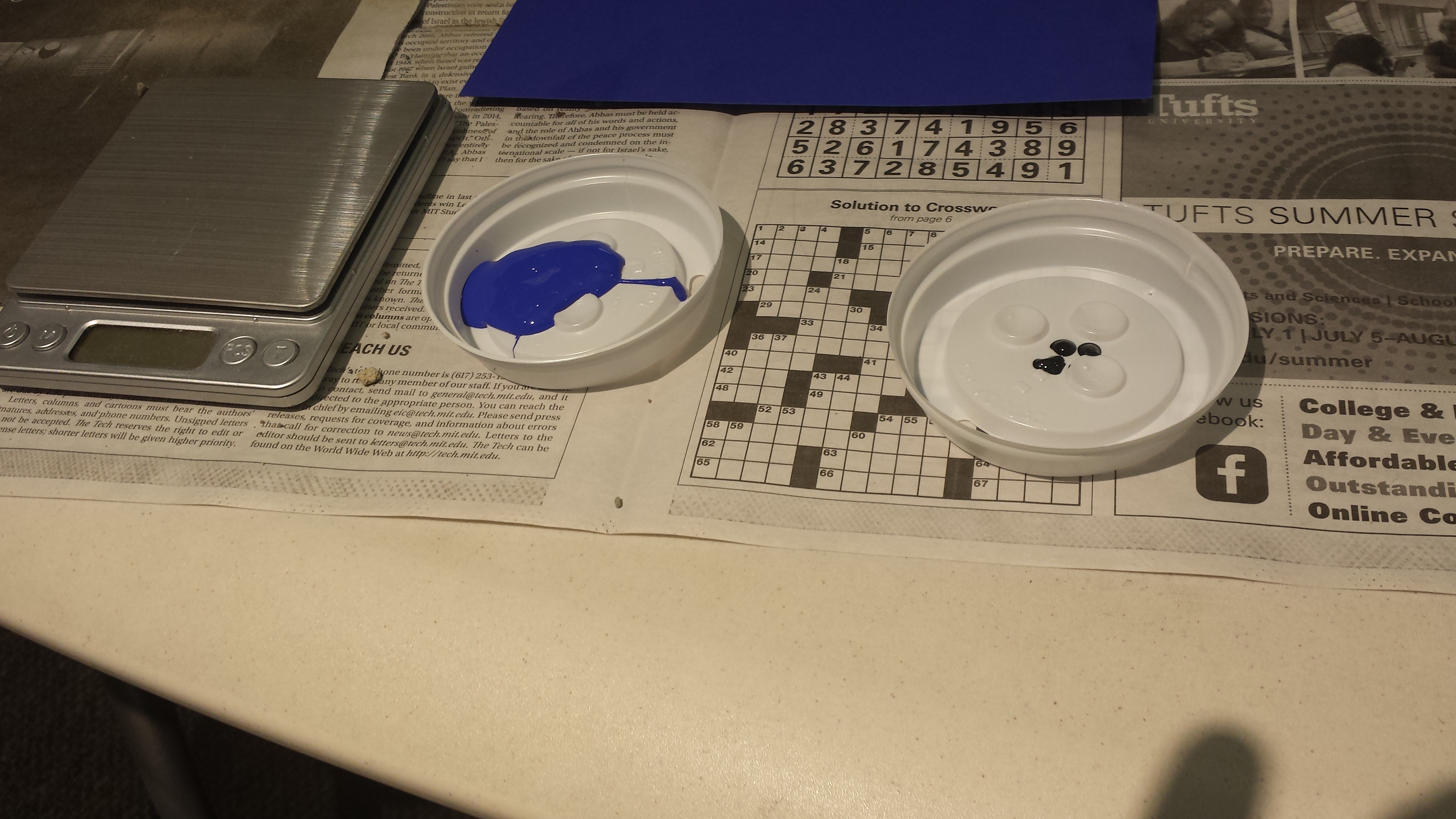
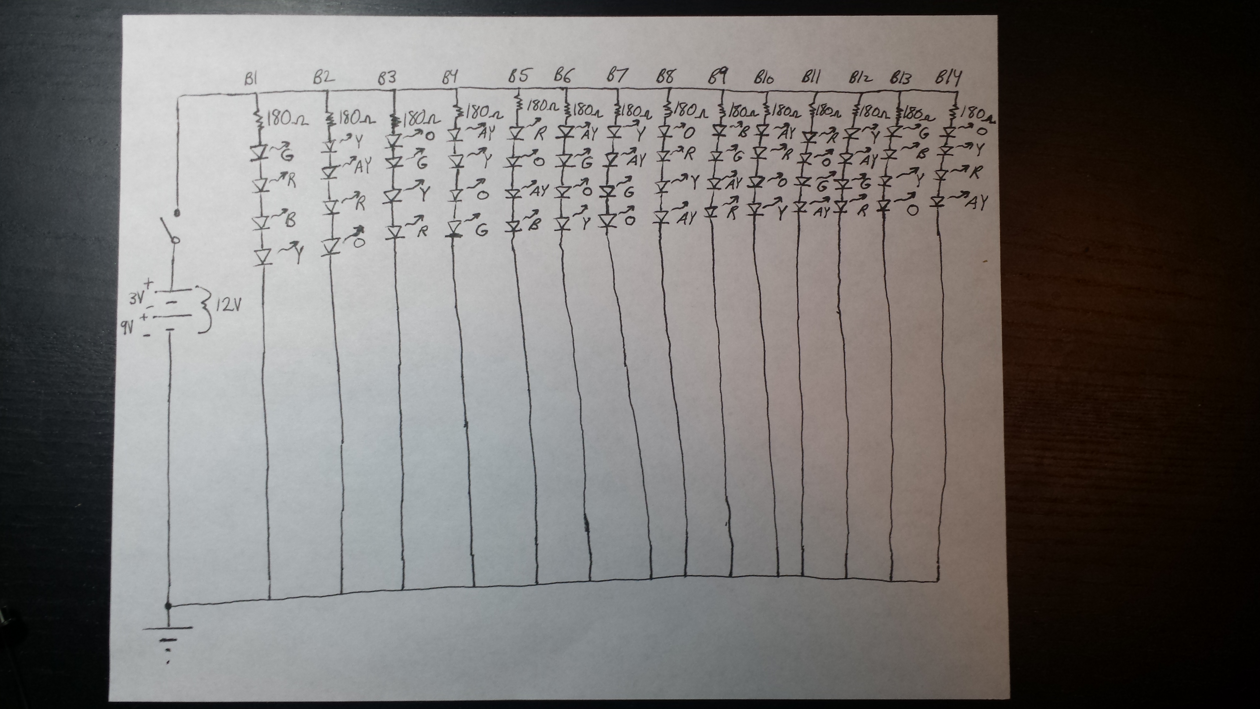
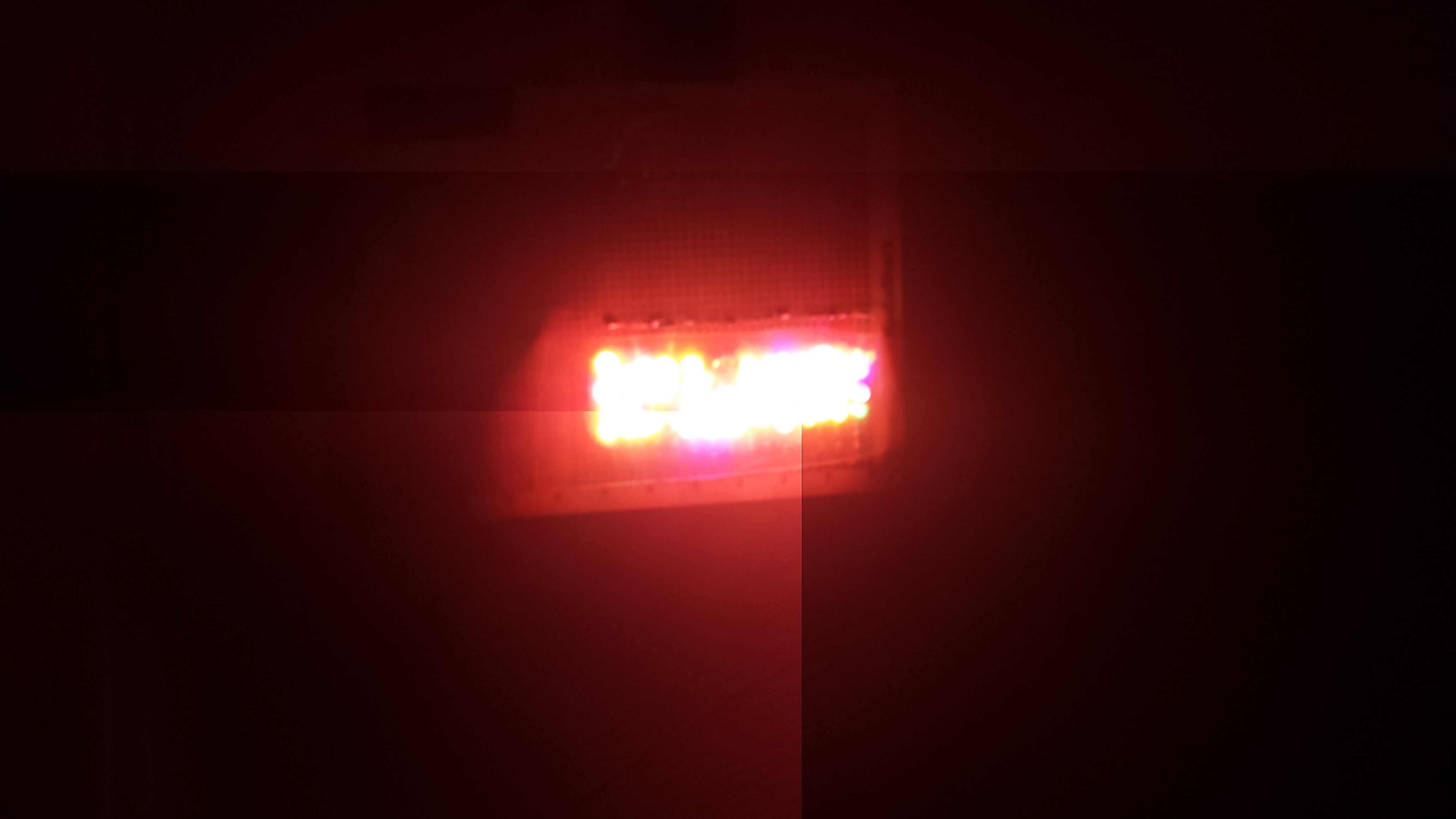
The Moon’s spectrum, shown as a blue line, was taken with the Moon at an altitude of 57 degrees. The red line on the diagram is the Sun’s spectrum at an altitude of 30 degrees. As seen, the two are markedly different over most of the visible spectrum. Six different colors of LEDs were placed in the circuit: blue at 467 nm, green at 522 nm, yellow at 592 nm, amber yellow at 595 nm, orange at 609 nm, and red at 660 nm. To develop my circuit, I first wrote down the signal strength for each of the colors from the spectrum. To the nearest tenth, I obtained: blue- 0.4, green- 0.9, yellow- 1.1, amber yellow- 1.1, orange- 1.1, and red- 1.0. Next, each of these numbers was multiplied by ten to yield the number of LEDs of each respective color; the total number of LEDs was thus 4+9+11+11+11+10 = 56. Since 56 is divisible by 4, I elected to set up the circuit with 14 parallel branches of 4 LEDs per branch. Desiring an even spread of the different colors to produce as monochromatic an appearance as possible, the process I used of arranging the locations of each LED was in no way random. Instead, I played a Sudoku-like game by requiring that each branch not contain more than one of each color, while limiting the number of same-color LEDs in each of the four rows to 3. To limit the current flowing through the LEDs, a 180 ohm resistor was positioned at the beginning of each branch. A 9 Volt battery and a 3 Volt battery pack were connected together in series to provide a total of 12 Volts to the circuit. Connected to the anode of the 3 Volt battery pack was a switch; the switch enables the wizard to easily turn on and off the LEDs by closing and opening the circuit. A picture of the complete circuit is illustrated below. The resistors and LEDs were all electrically connected by soldering on a RadioShack printed circuit board. For the body of my staff, I selected a six-foot tall cylindrical wooden pole. On top of this pole was mounted the assembled printed circuit board, along with the batteries. Over the LEDs a piece of plastic was taped down to diffuse the emanating light; a plastic bag was further placed over the board to help accomplish this task.

Staff Circuit

The door to be unlocked was a wooden circular one with a diameter of 4 inches. This door was part of a rectangular box, all six sides of which were laser cut and attached with Gorilla Glue. The box was designed in Onshape with grooves and protruding edges for the attachment. A picture of the design may be examined below. The shorter side that is visible on the right of the picture shows a large circular opening. After laser cutting all six sides I kept the cut-out circle from this piece to employ as the door. The shorter side not visible on the left is solid without a cut-out door. Notice also the small hole on the top piece. This is the entry point for light to enter the system. In my actual setup, I positioned this hole on the left side. I screwed on a hinge to the door and also attached a sliding lock to its interior side. On the front of the door, opposite the lock were four screws, one of which I attached to a bolt to form a door handle. The unlocking mechanism was a high-torque servo motor with a line of plastic tubing tied to the moving part of the lock. To digitally connect with the motor an Arduino Leonardo microcontroller board was used.

Box

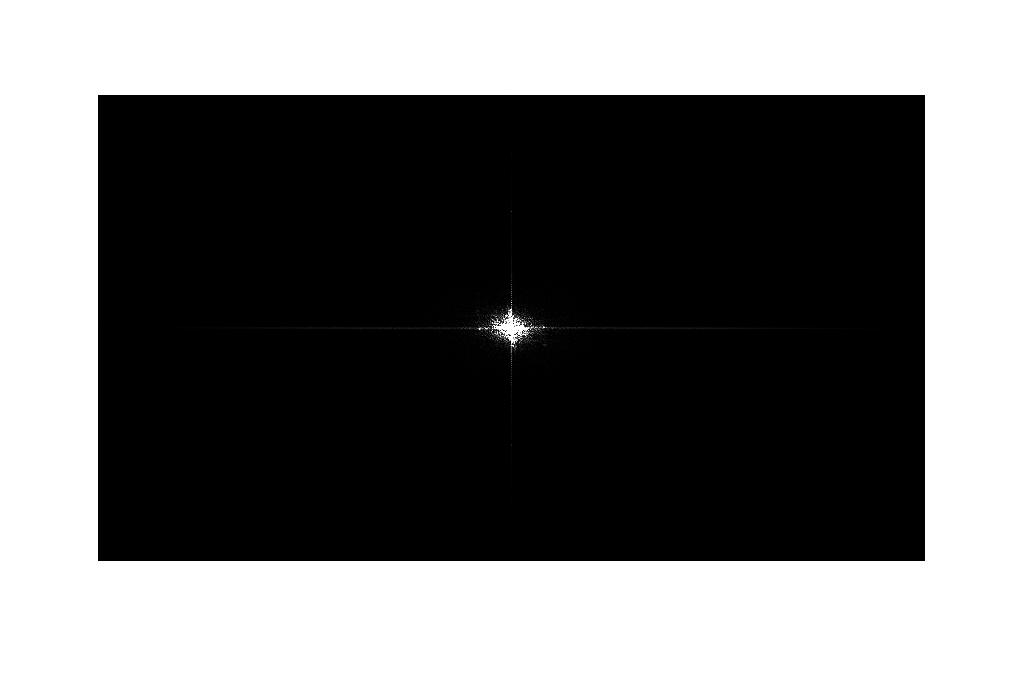
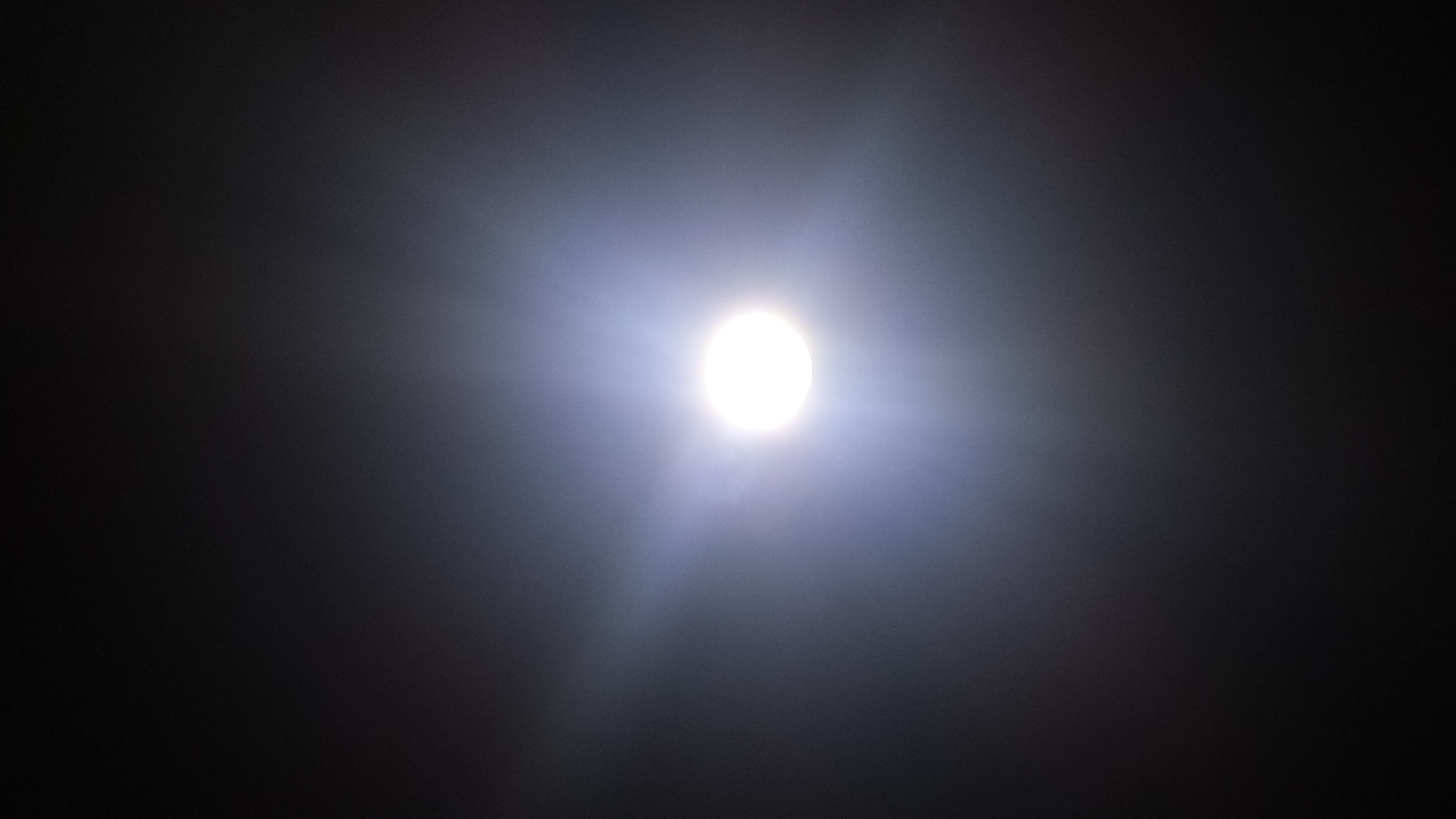
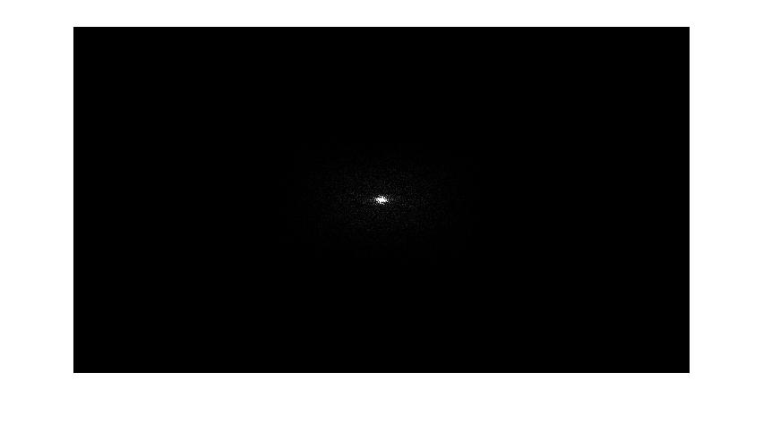
There exist a variety of methods of sensing light. One approach I strongly considered was to implement a Fast Fourier Transform on images of the light using Matlab. The Fourier Transform of a source of illumination reveals its spectrum. Below are images and corresponding shifted FFTs of both the light fixture atop my staff and an LED flashlight. Observing the differences in the two FFTs, it is clear that a comparator program would have distinguished between moonlight and sunlight in this case. Some of the challenges with this approach, however, are lag time of the computer for processing the images and running Matlab and Arduino software programs in concert. A simpler approach, and the one I implemented, is to exclusively use Arduino with photodetectors.

Staff

StaffFourier

flashlight

FlashlightFourier

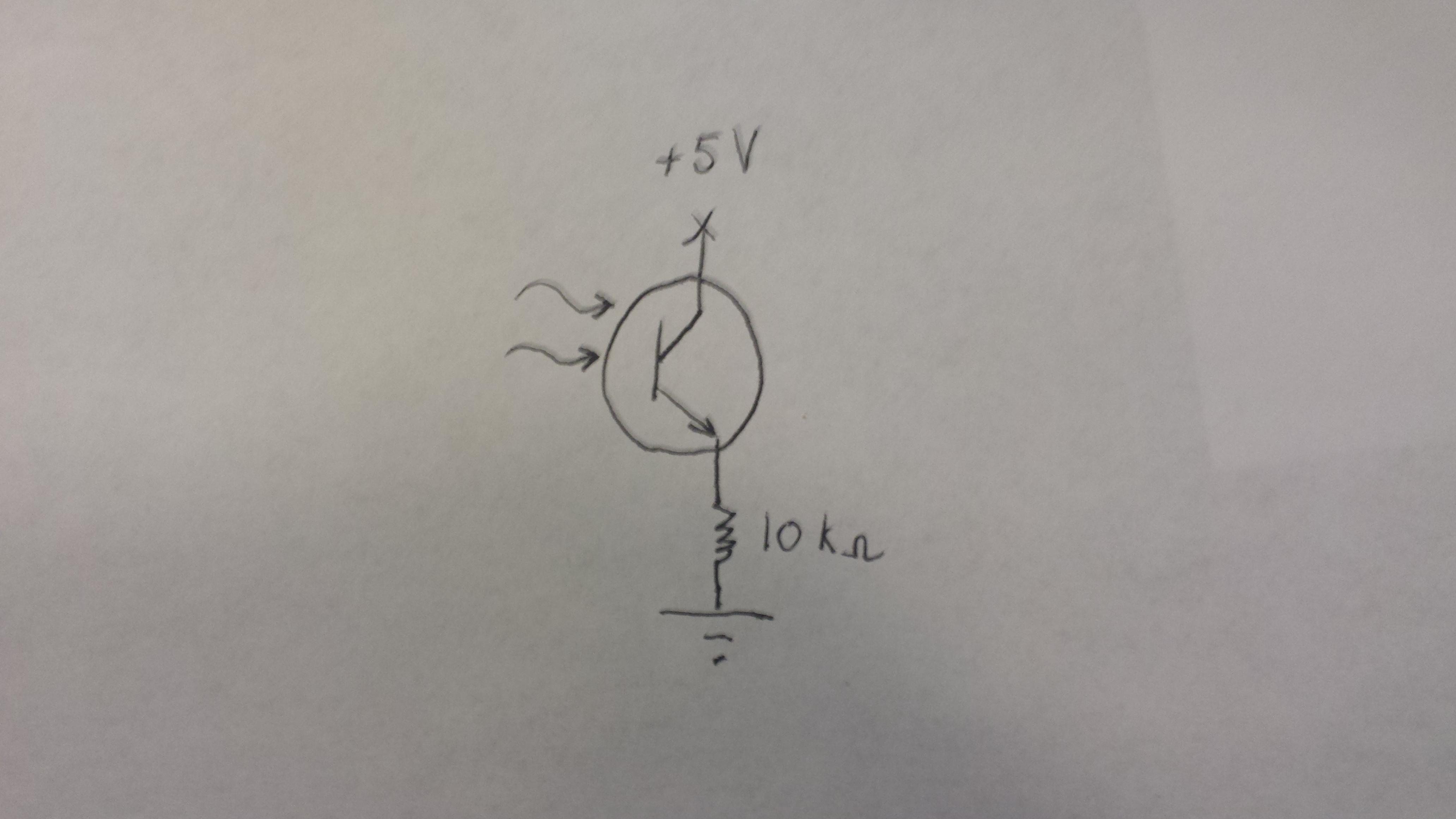
For the light sensor circuit, I considered photodiodes, phototransistors, and photocells for the light-detecting device. Connecting a photodiode in reverse-bias to a resistor without an operational amplifier in the circuit proved dreadful. The data received from the Arduino was intermittent; quite often the device would not output any signal unless I hovered a light source extremely close to it. I quickly came to the conclusion that an alternative device was necessary to obtain successful readings. Thus, I tested a 570 nm peak responsivity phototransitor. This worked remarkably well, as ambient lighting yielded a low analog reading in comparison to my moonlight staff. Furthermore, when I switched from the staff to a bright LED, I witnessed an order of magnitude increase in the value. The values read for different light sources with photocells were more uniform; however, photocells excelled at reproducing the same value for a given light source. My final system features a phototransitor in the configuration drawn below with a 10 kilo-ohm resistor.

Phototransistor Circuit

In my program, I use a digital bandpass filter to declare moonlight to be identified when my given value (analog read signal multiplied by one million) is between 650 million and 750 million. Under that condition, the servo activates to unlock the door. The following video features me testing a variety of light sources in addition to my staff. Notice that before testing begins, I tilt the box to the right to lock it. If, for whatever reason, I am unable to open the door, I can manually tilt the box to the left to slide the lock back towards the center of the door; this prevented me from being permanently locked out. As shown in the video, when the moonlight illuminated staff is placed over the keyhole, the arm on the servo motor rotates and the door unlocks. Upon entering through the door that resembles that of a Hobbit’s home, one can view the electronic devices- Arduino Leonardo, breadboard with components, and servo motor- and associated wiring that enable the system to function.


The moonlight illuminated staff I created fits well as a natural model. Just as the Sun is far brighter than the Moon, the colored LEDs on my staff produce light of a lesser intensity than bright LEDs. I have thoroughly enjoyed the liberation to explore a topic that intrigued me greatly after reading Tolkien’s works. In the process, I have learned a great bit of science, especially regarding astronomy, as well as the magical significance of moonlight as a trigger.

The Magic Mirror

Introduction:
The Magic Mirror is a spin off of my previous work with facial animation from last week. However I made a massive jump from purely digital art, modeling and animation to a full on software application for live facial recognition. This project is inspired by the sassy character in Dreamwork’s Shrek, but any image with a clear picture of a face in it could be used with the facial recognition algorithm I’m using.

Resources:
The open source github of what I have done can be found at: https://github.com/emvanb/MagicMirror
This work builds upon Kyle McDonald’s ofxFaceTracker and aturo’s FaceSubstituion libraries.

My Experiences:
This project was a pretty extreme stretch for me. Especially since when I proposed this idea, I didn’t yet know that facial image recognition and capture would be such a niche field with software that costs up to $10,000. Me being a naive but passionate CS undergrad at MIT, I should have recognized that I was a little in over my head.

when I started this project, I figured it would be difficult, but not infeasible. After many hours of researching on the web, and asking companies for free trials of their software, I realized that this mirror might be closer to infeasible than difficult.
I had done work with capturing body movements before with the XBOX Kinect for another Media Lab project called BodyPaint:
https://www.youtube.com/watch?v=Em9zXr30LlE
It was my mistake to assume capturing the motion of an arm or foot would be similar, since facial recognition is in the art of detail. Instead of using the XBOX Kinect, it seemed like just focusing on detailed images from a camera would be my best shot.

I eventually gave up on looking for pre-made applications online, as none of it was free and all of it required some elaborate set up. It was during this point that I stumbled across an openFrameworks add-on that I could use for facial tracking, along with a project that was being used to map on peoples faces over a camera. It wasn’t quite what I had in mind, but it was close enough. I dug around in the code to turn off all possibility of the camera showing a face, and changed the shader such that the mask didn’t attempt to blend it’s color with my skin. I also increased the strength of the masked color and turned the background black. I then fixed the modeling of my mask and took a picture of it so that I could import it into the software. After numerous tests I deemed it the best it could be at for presentation, and started training my voice actor to use the app. For some reason, the software was better at picking up my smaller rounder face than his longer one, but after some careful calibration we found what light source was needed, distance to screen necessary, and head movements would be best in order to not loose tracking.

For the monitor display I went to Blick to buy fancy gold paper and cardboard to frame a large 48″ HD screen with a half silvered mirror on top (Most of the frame was packing and duct tape from the back, but hey it worked). I then took some black cloth and draped it over the front bottom part of the mirror, so the audience couldn’t see the set up behind. The set up behind the mirror consisted of two lamps with extremely carefully dampened light in various positioning, a laptop connected to the HD TV with an HDMI cable, and my friend Yousef Alowayed who would serve as the voice behind the mirror. An extremely special thank you to Yousef. He’s an undergrad just like me, and took time out of his extremely busy finals week to help me with my Grad class project and listen to my attempts at directing him on how to move his face and where to sit.

Conclusion:
Overall this project was (in my opinion) a pretty big success. I was able to manipulate a program that was very difficult for me to understand to somewhat follow what some insanely expensive software does in industry. It was a very valuable learning experience, and quite the hilarious portfolio piece. I would like to thank my professors and mentors Dan Novy and V. Michael Bove for helping and encouraging me throughout this project, especially since they probably already knew this was going to be a long shot. Also special thanks to Anthony Kawecki and Anthony Occidentale for helping me throughout this class and for listening to me nonstop rant about how my mesh was detaching from my rigging, Maya was failing, and facial tracking was glitching for the past several weeks.

Note: The second movie referenced in the above video is Finding Dory to be released by PIXAR, not Disney.

Moonlight over the Doors of Durin

As an admirer of J.R.R. Tolkien’s Middle-Earth, I strove to replicate his hidden message on the Doors of Durin, which is the western entrance to the Dwarven city of Khazad-dûm.  These Doors were only visible with starlight and moonlight, and so could not be seen by sunlight during the day.  To generate moonlight I implemented a materials-based approach.  My rationale for this was due to the fact that moonlight has a spectral signature not limited to a single wavelength.  This is quite logical, as moonlight is largely reflected sunlight off the Moon’s surface, and sunlight extends over the entire electromagnetic spectrum. In 1929, French astronomer Bernard Lyot made a volcanic ash mixture with identical optical characteristics as the lunar rocks.  Specifically, he illustrated a near-perfect match of light polarization among the two materials over all phase angles.

I made a model of the Moon by gluing volcanic ashes from St. Helena on a green Styrofoam sphere with a spray adhesive.  The circumference of the sphere prior to applying the ashes was approximately 31 centimeters; after gluing the ashes, the circumference increased to 33 centimeters.  Therefore, on average, the thickness of the ash layer on my model Moon is 2 centimeters.  To elevate the Moon over a surface, I stuck one end of a wooden dowel through part of the Styrofoam, such that my model looked like a lollipop.  The other end of the dowel was put into a green Styrofoam rectangular prism that rested on the table.  Below is a picture of this constructed model.

Model Moon

To compare my model with the actual Moon, I determined the intrinsic brightness of both objects using the equation:

Albedo Equation

Here, A is the albedo (which is the fraction of incident light reflected off the Moon), H is the absolute magnitude (the brightness of the Moon if positioned one astronomical unit away; this distance is about the distance from the Earth to the Sun: 1 AU = 149,597,870,700 meters), and D is the Moon’s diameter in kilometers.  The Moon’s albedo is approximately 12 percent.  Substituting this value into the above equation and calculating the diameter by dividing the circumference by pi and converting to kilometers (D = 1.0504 x 10⁻⁴ km), the absolute magnitude for my model Moon is H = 37.8129.  The absolute magnitude for the real Moon is quoted as HMoon = 0.25.  Objects that are intrinsically brighter than others have a lower absolute magnitude; the absolute magnitude can even be a negative quantity for very bright materials.  It is evident from the above equation that the diameter and absolute magnitude are related in a logarithmic fashion.  To find how many times brighter the model Moon is than the actual Moon, simply take the fifth root of 100

Fifth Root

and raise it to the power of the positive difference between the absolute magnitudes.  Thus, the Moon is

Brightness Equation

≈ 1.06145×10¹⁵ times brighter than my sphere made with volcanic ash.

To produce an ink that was invisible under illumination by sunlight but visible under moonlight, I resorted to a contrast scheme.  That is, I applied ink of nearly identical color as the parchment I wrote on.  The catch is that the ink needed to be slightly different than the paper with an additional color component to differentiate between the Sun and Moons’ spectra.  Sunlight consists of equal parts of red, green, and blue components.  Moonlight, however, possesses a noticeably stronger red component and a weaker blue component.  Many people are oblivious of this fact; the reasoning deals with the Purkinje effect, which makes objects in darker settings appear bluer to us, as a result of the rods in human eyes.

Knowing that the Purkinje effect would not prove a significant issue with a light source positioned near my Moon to brightly reflect on my parchment, I tried two different contrast schemes.  One used blue paper with a blue ink that had a tinge of black added.  The second used black paper with black ink that had a tinge of red added.  The inks were mixed and applied using a paintbrush.  Upon writing with the inks, I quickly realized that they had a different color than their corresponding parchments even before the mixing of a secondary color.  Thus, testing was performed to make inks of exactly the same colors as the blue and black parchments.  I began with a rough test, simply adding spoonfuls of primary ink to dabs of secondary ink.  After doing this, I recognized that a stricter method was necessary.  My first attempt to yield a more precise test was to use eye droppers and simply count the number of drops I added of each color.  This plan was squashed, however, upon noticing that the ink was too viscous to exit the droppers.  My alternative approach made use of a scale to weigh quantities of the primary colors; below is a picture of the scale measuring one gram of blue ink.

Scale

As mixing a quantity of the secondary color that was undetectable with the scale with several grams of the primary color went very far in changing the resultant color, and understanding that I did not want to devote an umpteen number of grams of primary ink for each trial, I carefully made depressions with a chopstick for my measure of the secondary ink.  Shown below are typical quantities of the two inks; notice the three depressions of the black ink.

Ink Quantities

Pictures of the ink tests are shown below.  The first picture shows the rough test performed with spoonfuls of blue ink and large dabs of black ink.  All the character sets are labels, each written with one spoonful of blue ink: B is blue (no black), 1W is one spoonful of blue ink mixed with one dab of white ink, 2W has two dabs of white ink,…, 4B has two dabs of black ink, and 5B has 5 dabs of black ink.  Don’t be fooled by the apparent disappearance of the 4W and 5W in the photo.  From the proper viewing angle, they both are quite bright, and clearly not the same color as the parchment.  The second picture validates this assertion.  Notice how bright the 4W and 5W are here.  This picture contains additional tests.  The W on the top right denotes plain white ink, clearly visible in comparison to all other colors.  Looking closely at the middle of the page, one can spot the character sets 1g, 2g, 3g.  These represent grams of blue ink mixed with exactly 10 depressions of black ink.  By my inspection, I determined that the 3g appeared the least noticeable.  Therefore, I used the recipe of 3 grams blue ink mixed with 10 chopstick depressions of black ink to write the hidden message.  The third picture shows testing done with the black ink.  This was less extensive for two reasons.  One, the black ink more closely matched the black parchment to begin with.  And two, by the time I began testing on the black parchment, I had already performed extensive testing with the blue parchment, so I proceeded directly with using the scale.  The code on this sheet is: B- black ink only, 1gB3R- 1 gram black ink and 3 depressions of red ink, and 1gB4R- 1 gram black ink and 4 depressions of red ink.  To write the hidden message, I chose 1gB3R as my recipe, as the extra amount of red in 1gB4R resulted in an ink that appeared more visible in ordinary light, without any noticeable improvement under moonlight.

Blue Ink Test Start

Blue Ink Test Detailed

Black Ink Test

The secret message I wrote on both the blue and black parchments is the same one that appears on the Doors of Durin.  It is written in the language of the Elves.

Ennyn Durin Aran Moria.

Pedro mellon a Minno.

Im Narvi hain echant.

Celebrimbor o Eregion tethant i thiw hin.


This translates in English as


The Doors of Durin, Lord of Moria.

Speak, friend, and enter.

I, Narvi, made them.

Celebrimbor of Hollin drew these signs.


Below are pictures of this message written in Elvish on both colored parchments.

Secret Message

To represent the Sun, I employed an LED flashlight with a luminous flux of 37 lumens.  The Sun has a luminous flux of 3.6×1028 lumens; that is on the order of 10 thousand yottalumens (Ylm).  Given that the distance from the Moon to the Sun ranges from about 147 million kilometers to 152 million kilometers, thereby taking a rough average of 150 million kilometers, in order for the ratio of luminous flux to distance to be equivalent for my contrived system, the LED flashlight must be placed approximately 1.5417×10⁻¹⁶ meters from the model Moon.  This is quite fascinating but hardly an issue, as the light loss over reasonable distances of several meters is minimal.

By turning each parchment at an angle with respect to the flashlight, the writing appeared invisible.  Examine the three pictures below for the blue and black parchments to verify this.

Blue Black Invisible

Blue Sunlight

Black Sunlight

To produce moonlight the flashlight was shined on the volcanic ash sphere.  For the effect to be astounding, one should already place the parchment at a viewing angle such that it is invisible with the flashlight shining on it, and merely move the Moon into the light path without shifting the parchment at all.  The two pictures below were taken exercising this approach; the first is the blue parchment and the second is the black parchment, both under moonlight.  Observe that since the Moon I constructed is small in relation to the parchment, the message is not entirely visible.  One must shift the paper towards the Moon to read content on the right-hand side.  Nevertheless, you can still pretend to be Gandalf.

Blue Moonlight

Black Moonlight

The challenge, of course, is to develop an ink that is invisible under sunlight for all viewing angles, not just a restricted angular range, and that is also clearly seen under moonlight.  I will endeavor to rectify this problem for my final project.