Category Archives: Projects

Through the Keyhole and Into the Shire

doorsofdurin

Historically, one of the oldest references to a magical wand describes the supernatural item in the form of a staff. Staffs, if not too ornate, provide their owners with a lethal weapon that many observers would regard as an ordinary walking stick. For my final project, I have assembled a moonlight illuminating staff with the power to unlock a door. This idea of unlocking doors with moonlight stemmed in part from the wondrously entertaining, magical adventure novel, The Hobbit by Tolkien. In the story, the protagonists are given the following clue to enter the Lonely Mountain and reclaim their treasure from the treacherous dragon, Smaug: “’Stand by the grey stone when the thrush knocks’, read Elrond, ‘and the setting sun with the last light of Durin’s Day will shine upon the key-hole.’” The last light actually alludes to the setting sun in the book; the movie embellishes the riddle by declaring moonlight alone to be the last light of Durin’s Day.
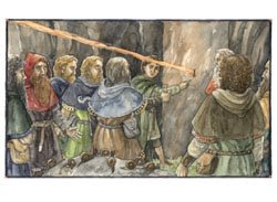
durins_day_thMoonlight does, however, play a vital role in the novel, as Durin’s Day is, “when the last moon of Autumn and the sun are in the sky together.”
The technique chosen for developing a light source mimicking moonlight was to wire a multitude of colored LEDs together such that the number of each color was proportional to the relative intensity at that particular wavelength in the spectrum for moonlight. With only a finite number of different colors of LEDs in the circuit, the light source would serve as an approximation of moonlight. However, by inserting a sufficiently high number of LEDs into the circuit and extending the variety of colors fairly evenly across the visible region of the spectrum, this approximation should be sufficient. The spectrum that I used to determine the number of each color, originally from a paper by Ciocca & Wang, can be viewed at the following link:

http://physics.stackexchange.com/questions/244922/why-does-moonlight-have-a-lower-color-temperature

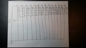
The Moon’s spectrum, shown as a blue line, was taken with the Moon at an altitude of 57 degrees. The red line on the diagram is the Sun’s spectrum at an altitude of 30 degrees. As seen, the two are markedly different over most of the visible spectrum. Six different colors of LEDs were placed in the circuit: blue at 467 nm, green at 522 nm, yellow at 592 nm, amber yellow at 595 nm, orange at 609 nm, and red at 660 nm. To develop my circuit, I first wrote down the signal strength for each of the colors from the spectrum. To the nearest tenth, I obtained: blue- 0.4, green- 0.9, yellow- 1.1, amber yellow- 1.1, orange- 1.1, and red- 1.0. Next, each of these numbers was multiplied by ten to yield the number of LEDs of each respective color; the total number of LEDs was thus 4+9+11+11+11+10 = 56. Since 56 is divisible by 4, I elected to set up the circuit with 14 parallel branches of 4 LEDs per branch. Desiring an even spread of the different colors to produce as monochromatic an appearance as possible, the process I used of arranging the locations of each LED was in no way random. Instead, I played a Sudoku-like game by requiring that each branch not contain more than one of each color, while limiting the number of same-color LEDs in each of the four rows to 3. To limit the current flowing through the LEDs, a 180 ohm resistor was positioned at the beginning of each branch. A 9 Volt battery and a 3 Volt battery pack were connected together in series to provide a total of 12 Volts to the circuit. Connected to the anode of the 3 Volt battery pack was a switch; the switch enables the wizard to easily turn on and off the LEDs by closing and opening the circuit. A picture of the complete circuit is illustrated below. The resistors and LEDs were all electrically connected by soldering on a RadioShack printed circuit board. For the body of my staff, I selected a six-foot tall cylindrical wooden pole. On top of this pole was mounted the assembled printed circuit board, along with the batteries. Over the LEDs a piece of plastic was taped down to diffuse the emanating light; a plastic bag was further placed over the board to help accomplish this task.

Staff Circuit

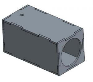
The door to be unlocked was a wooden circular one with a diameter of 4 inches. This door was part of a rectangular box, all six sides of which were laser cut and attached with Gorilla Glue. The box was designed in Onshape with grooves and protruding edges for the attachment. A picture of the design may be examined below. The shorter side that is visible on the right of the picture shows a large circular opening. After laser cutting all six sides I kept the cut-out circle from this piece to employ as the door. The shorter side not visible on the left is solid without a cut-out door. Notice also the small hole on the top piece. This is the entry point for light to enter the system. In my actual setup, I positioned this hole on the left side. I screwed on a hinge to the door and also attached a sliding lock to its interior side. On the front of the door, opposite the lock were four screws, one of which I attached to a bolt to form a door handle. The unlocking mechanism was a high-torque servo motor with a line of plastic tubing tied to the moving part of the lock. To digitally connect with the motor an Arduino Leonardo microcontroller board was used.

Box

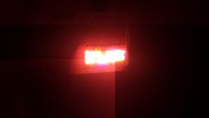
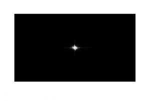
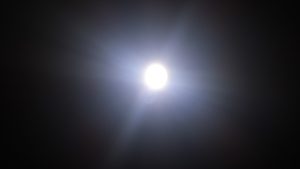
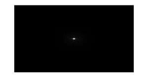
There exist a variety of methods of sensing light. One approach I strongly considered was to implement a Fast Fourier Transform on images of the light using Matlab. The Fourier Transform of a source of illumination reveals its spectrum. Below are images and corresponding shifted FFTs of both the light fixture atop my staff and an LED flashlight. Observing the differences in the two FFTs, it is clear that a comparator program would have distinguished between moonlight and sunlight in this case. Some of the challenges with this approach, however, are lag time of the computer for processing the images and running Matlab and Arduino software programs in concert. A simpler approach, and the one I implemented, is to exclusively use Arduino with photodetectors.

Staff

StaffFourier

flashlight

FlashlightFourier

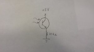
For the light sensor circuit, I considered photodiodes, phototransistors, and photocells for the light-detecting device. Connecting a photodiode in reverse-bias to a resistor without an operational amplifier in the circuit proved dreadful. The data received from the Arduino was intermittent; quite often the device would not output any signal unless I hovered a light source extremely close to it. I quickly came to the conclusion that an alternative device was necessary to obtain successful readings. Thus, I tested a 570 nm peak responsivity phototransitor. This worked remarkably well, as ambient lighting yielded a low analog reading in comparison to my moonlight staff. Furthermore, when I switched from the staff to a bright LED, I witnessed an order of magnitude increase in the value. The values read for different light sources with photocells were more uniform; however, photocells excelled at reproducing the same value for a given light source. My final system features a phototransitor in the configuration drawn below with a 10 kilo-ohm resistor.

Phototransistor Circuit

In my program, I use a digital bandpass filter to declare moonlight to be identified when my given value (analog read signal multiplied by one million) is between 650 million and 750 million. Under that condition, the servo activates to unlock the door. The following video features me testing a variety of light sources in addition to my staff. Notice that before testing begins, I tilt the box to the right to lock it. If, for whatever reason, I am unable to open the door, I can manually tilt the box to the left to slide the lock back towards the center of the door; this prevented me from being permanently locked out. As shown in the video, when the moonlight illuminated staff is placed over the keyhole, the arm on the servo motor rotates and the door unlocks. Upon entering through the door that resembles that of a Hobbit’s home, one can view the electronic devices- Arduino Leonardo, breadboard with components, and servo motor- and associated wiring that enable the system to function.


The moonlight illuminated staff I created fits well as a natural model. Just as the Sun is far brighter than the Moon, the colored LEDs on my staff produce light of a lesser intensity than bright LEDs. I have thoroughly enjoyed the liberation to explore a topic that intrigued me greatly after reading Tolkien’s works. In the process, I have learned a great bit of science, especially regarding astronomy, as well as the magical significance of moonlight as a trigger.

The Magic Mirror

Introduction:
The Magic Mirror is a spin off of my previous work with facial animation from last week. However I made a massive jump from purely digital art, modeling and animation to a full on software application for live facial recognition. This project is inspired by the sassy character in Dreamwork’s Shrek, but any image with a clear picture of a face in it could be used with the facial recognition algorithm I’m using.

Resources:
The open source github of what I have done can be found at: https://github.com/emvanb/MagicMirror
This work builds upon Kyle McDonald’s ofxFaceTracker and aturo’s FaceSubstituion libraries.

My Experiences:
This project was a pretty extreme stretch for me. Especially since when I proposed this idea, I didn’t yet know that facial image recognition and capture would be such a niche field with software that costs up to $10,000. Me being a naive but passionate CS undergrad at MIT, I should have recognized that I was a little in over my head.

when I started this project, I figured it would be difficult, but not infeasible. After many hours of researching on the web, and asking companies for free trials of their software, I realized that this mirror might be closer to infeasible than difficult.
I had done work with capturing body movements before with the XBOX Kinect for another Media Lab project called BodyPaint:
https://www.youtube.com/watch?v=Em9zXr30LlE
It was my mistake to assume capturing the motion of an arm or foot would be similar, since facial recognition is in the art of detail. Instead of using the XBOX Kinect, it seemed like just focusing on detailed images from a camera would be my best shot.

I eventually gave up on looking for pre-made applications online, as none of it was free and all of it required some elaborate set up. It was during this point that I stumbled across an openFrameworks add-on that I could use for facial tracking, along with a project that was being used to map on peoples faces over a camera. It wasn’t quite what I had in mind, but it was close enough. I dug around in the code to turn off all possibility of the camera showing a face, and changed the shader such that the mask didn’t attempt to blend it’s color with my skin. I also increased the strength of the masked color and turned the background black. I then fixed the modeling of my mask and took a picture of it so that I could import it into the software. After numerous tests I deemed it the best it could be at for presentation, and started training my voice actor to use the app. For some reason, the software was better at picking up my smaller rounder face than his longer one, but after some careful calibration we found what light source was needed, distance to screen necessary, and head movements would be best in order to not loose tracking.

For the monitor display I went to Blick to buy fancy gold paper and cardboard to frame a large 48″ HD screen with a half silvered mirror on top (Most of the frame was packing and duct tape from the back, but hey it worked). I then took some black cloth and draped it over the front bottom part of the mirror, so the audience couldn’t see the set up behind. The set up behind the mirror consisted of two lamps with extremely carefully dampened light in various positioning, a laptop connected to the HD TV with an HDMI cable, and my friend Yousef Alowayed who would serve as the voice behind the mirror. An extremely special thank you to Yousef. He’s an undergrad just like me, and took time out of his extremely busy finals week to help me with my Grad class project and listen to my attempts at directing him on how to move his face and where to sit.

Conclusion:
Overall this project was (in my opinion) a pretty big success. I was able to manipulate a program that was very difficult for me to understand to somewhat follow what some insanely expensive software does in industry. It was a very valuable learning experience, and quite the hilarious portfolio piece. I would like to thank my professors and mentors Dan Novy and V. Michael Bove for helping and encouraging me throughout this project, especially since they probably already knew this was going to be a long shot. Also special thanks to Anthony Kawecki and Anthony Occidentale for helping me throughout this class and for listening to me nonstop rant about how my mesh was detaching from my rigging, Maya was failing, and facial tracking was glitching for the past several weeks.

Note: The second movie referenced in the above video is Finding Dory to be released by PIXAR, not Disney.

Link

For the “Trick++” assignment, I wanted to use the computer as the magician.

Our group recently purchased a couple of Tobii eyex eyetrackers and this was a great opportunity for me to learn how to use one.

The magic worked as follows:
The audience member volunteered was asked to sit in front of the computer screen, which showed an animation of shuffling deck of cards.
When the volunteer is ready he/she clicks the “Magic” button and the computer shuffles the cards and open the top 5. Then, a short tune is starting to play and the user should now choose one card and concentrate on it really hard – “transmit your choice to the computer”.
After 10 seconds the music is over. The deck of card is again shuffled and then all the cards in the deck are spread on the screen, all facing down but the chosen card that is facing up.

The method:
The eye tracker at the bottom of the screen is tracking the user eyes while the cards are open and music is played. The chosen card is the one that the user looked on for the longest time.
The code for the webpage running the magic is here.
And the server I used for reading data from Tobii to javascript is from here.
 

Kinect Hand Gesture Magic Trick

For my cyber-magic project I created a Kinect based magic trick that included hand tracking. This project was done in Scratch and in order to connect the Xbox Kinect I used an add on called Kinect2Scratch4Mac.

Effect: Make it seem like I’m creating digital blue sparkles shoot out behind my hands on a screen I’m standing in front of. Magically I make it appear that I have grabbed the sparkles off of the screen when I ball my hands into fists and the sparkles stop. I then throw the sparkles into the real physical world.

Method: I used a kinect to track my left and right hands. When my hands were above a certain point on the y-axis (around my shoulder height) I activated sparkles that followed the hands on the screen background. The secret to stopping the sparkles was through use of a counter. I was timing my whole performance in my head. As soon as my counter was up based upon how long my left hand was below my shoulder level, I knew that the next time I lifted my hands, the sparkles would be gone. This is when I closed my hands into fists. The second trick was to hold glitter between my fingers the entire performance without letting the audience know. Once my hands were in fists and I opened them again, the audience sees the glitter but thinks it is coming out of thin air.

The code is posted here on scratch.com so you can all see how it works 🙂

https://scratch.mit.edu/projects/99906456/

Final Project Documentation — Let There Be Light

Magic Final Documentation

###############################################################
Script of the trick:
###############################################################
*magician stands next to a table with a black TV screen (facing the audience) and a black box*

The wizards of legend had amazing powers: the ability to make things disappear, the ability to move things without touching them, the ability to fly. In comparison, the “magic” performed by current magicians is trivial: sleight of hand and clever contraptions to befuddle people. But I wanted to return to the time when being magical meant being powerful. As powerful as a God. And on the first day of creation, what did God say? Let there be light.

*magician waves hand over device sitting on the table in front of him*

*device starts shining brightly*

Of course magic is only magical if it transcends boundaries: the laws of physics, the expectations of common folk, and sometimes… real physical boundaries.

*Bring audience member on stage, hand them a silicon box made to look like steel*

(to audience member) This is a metal box, correct? Go ahead, pick it up and feel it. Can you confirm it’s made of real metal? Awesome, thanks. Go ahead and place that over the device. Now for those of you out there who aren’t big physics nerds, it isn’t possible to send any sort of signal through solid metal using any of the technologies in our cell phones, computers, and everything else. You see, metal reflects electromagnetic waves, so for anyone who thought I was doing something tricky with wireless communication, explain this one.

*wave hand over box*

(to audience member) Now, go ahead and remove the box.

*device is shining, cover it up again*

(repeat procedure, asking audience members whether to turn it on or off each time so they you know you truly have control over whether it turns on or off)

*excuse the audience member back to their seat*

When it comes to light, I’m a bit biased. I have a particular source of light that I prefer above all others: fire. That’s right, I’m a total pyro, proud of it. My runescape username was actually irishpyro94 for all of middle school. True story.

Now, as a natural element, fire is inherently more difficult to control that manmade light sources like those I was controlling before. This doesn’t always go well, so I’m going to back up from my target a little bit in case something goes wrong. *looks at people in front row* Um, you guys all turned in your liability waivers right? Ok, good.

*walk to other side of stage*

Alright, who want to see some fire!?

*gesture as if shooting a fireball a la Dragon Ball Z, TV screen suddenly turns on, showing a picture of a blazing fire, sound effects*

*applause*

Thank you!

###############################################################
End script
###############################################################

This trick gives the illusion of generating fire and light at one’s will. The script above describes the ideal version of the trick which I didn’t have time to fully implement unfortunately. I will describe the technology I used to perform a first approximation of the above.

There are two primary technical components: an infrared-based module for the up-close magic and a Bluetooth-based trick for the fire trick. I will discuss the infrared technology first.

########################
INFRARED
########################
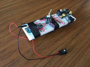
IR Transmitter
2015-05-17 16.06.36

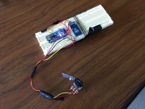
The magician needs an IR LED attached to his wrist with an appropriate power supply hidden up his sleeve. In my trick, I used a breadboarded Arduino circuit. I powered an Arduino Nano (http://www.arduino.cc/en/Main/ArduinoBoardNano) from a 9V battery. Then I passed the 5V rail through an appropriately sized resistor to limit the current, then through the IR led and finally to ground. I taped this LED to the bottom of my palm near my wrist, positioned such that it was covered up by the sleeves of my coat unless I extend my arms in front of me, as I do when flourishing my hands over the device in the trick. The LED I used turned out to be highly directional, only shining in a narrow beam. A better choice would be an omnidirectional light source, though then the magician would need a way to tell the LED when to turn on (as opposed to my setup, where the LED was always on). This could be accomplished with a flesh-colored flex sensor on the magician’s palm that can tell when the magician’s hand is flexed open.

IR Receiver

2015-05-17 16.06.56

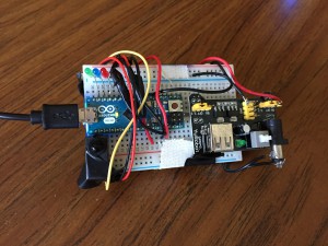
The device that actually lights up needs only 3 components: a power source, an IR sensor, and a light source. I used an Arduino Nano powered via USB from my computer, though in the ideal performance the device would be battery-powered. I used an IR sensor with an integrated thresholding circuit, but the sensitivity could be better tuned if a discrete photodiode was used with the output current being read by a microcontroller that does the thresholding calculation. For the light source, I used three standard LEDs, one of each red, green, and blue. This results in an interesting iridescent effect because your eye doesn’t know whether to interpret the light as white or as discrete colors.

Ideally, this device would be packaged in an interesting way, perhaps to look like an orb or crystal ball of some sort, like the one in Gandalf’s staff that he used in Moira and to drive away the Nazgul during the Gondorian retreat from Osgiliath.

The silicon box mentioned in the script is an interesting touch that I wish I could have implemented. Silicon is transparent at IR wavelengths, but opaque to visible light. I tried to leverage the fact that it looks like metal to convince any skeptics in the audience.

Here you can see the IR system in operation.

2015-05-17 16.09.57

########################
BLUETOOTH
########################
The final part of the trick involves “lighting the TV on fire”. This is done through Bluetooth signalling between the magician and the computer controlling the TV. In the script, I described a TV monitor to display the fire, but in the trick I performed, I used a laptop. Using a larger screen is better for dramatic effect, and if it can be powered wirelessly using resonant magnetic induction, that adds another impressive element to the trick, that would be extra impressive. Then there could be some banter about the energy of the fire powering the screen or something.

Bluetooth transmitter

2015-05-17 16.08.13

On the magicians side, there is an Arduino Nano wired to an HC-05 Bluetooth module (http://www.amazon.com/Bluetooth-converter-serial-communication-master/dp/B008AVPE6Q). The Arduino is continuously reading in analog voltage values from a potentiometer voltage divider circuit. These 0-5V voltages are converted to a 10-bit binary value (0-1024 in decimal). This decimal value is sent to the HC-05 using the SoftwareSerial Arduino module, and the HC-05 automatically transfers those values to the device with which it is paired. The magician need to discreetly rotate the potentiometer dial counterclockwise during the “fireball throwing flourish”, thus signalling to the TV to display fire. Alternatively, there can just be a discreet button and the Arduino can wait for it to be pressed, which would have been way simpler and more robust than the potentiometer method. Lesson learned.

The code for this is found at https://github.com/colinmcd94/magic/blob/master/magic_analog_tx/magic_analog_tx.ino.
For anyone who wants to use bluetooth communication for any reason, I have a skeleton file for using HC-05 with Arduino+SoftwareSerial here: https://github.com/colinmcd94/magic/blob/master/magic_bluetooth/magic_bluetooth.ino.

Bluetooth reciever
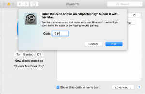
I paired my Mac with the HC-05 module, which is fairly easy to do from System Preferences. If the pairing initially fails, click Options and enter the code 1234 into the box. This is the default code for all HC-05 modules.

[Screenshot 2015-05-17 16.11.33

My computer was running a shell script that connected to the HC-05 serial port using the stty command and received a data packet every 2 seconds or so. This script can be found at https://github.com/colinmcd94/magic/blob/master/fire.sh. You can see the values written to the terminal change as I rotate the potentiometer knob, and when the values falls below 100 (corresponding to about half a volt), my computer opens Safari and shows a video of fire. This is a webpage I wrote available at http://mcdonnell.mit.edu/human/magicfire.html. It uses bigvideo.js to display a video across the whole screen.

Here, you can see the Bluetooth system in operation. You can see the decimal voltage readings being transferred to the shell script running in Terminal, and the “catching fire” in action.

2015-05-17 16.16.07

Final Project Documentation (Kenny Friedman)

Beginnings
My final project is the culmination of projects I’ve done throughout the semester using magic to tell stories. I started with a math-based card trick involving the Fibonacci sequence. Then, I augmented that trick with a fake-Siri and had an argument with my computer for my Trick++. Next, for my midterm project, I used the pre-recorded audio concept and applied it to audio and video across multiple screens (the projector, an iPad, and an iPhone). This was similar to Marco Tempest’s iPod illusion, except with vertical displays of multiple sizes.

IMG_2191Now, I’m taking the same concept of interacting with screens, except the audio and video is no longer pre-recorded. This allows for less precision as the act responds to the performer, as well as more options for audience interaction or mistakes.
I think using techno illusions to convey a concept is a really powerful medium. In the iPod illusion, Marco uses it (aptly) to discuss the concept of deception. I really enjoyed the meta level of using a concept to talk about the concept. Since my technology involves augmented reality (AR), I initially thought of talking about AR by using AR. However, after playing around with the story, I realized that a more general and universal concept like deception, empathy, or time is a better use of techno illusions. I decided to talk about time.

Finally, I tried to step into a magic circle to think about mediums that are rarely used in magic. After looking through different kinds of art and word play, I noticed that I couldn’t find many examples of poetry & magic. And, with the exception of Bo Burnham, I couldn’t find any examples of comedy*, poetry, and magic combined.

*not that my goal was to perform something humorous or anything.

Thoughts Behind the Technology

Marco Tempest’s MultiVid ( http://marcotempest.com/screen/Public_MultiVid ) is a fantastic piece of software, however it’s limited to videos on iOS devices. The videos sync, but they can’t interact. I wanted to make a framework that allowed incorporated many aspects of an interactive multimedia performance.

I ended up successfully implementing three interactive multimedia elements. They are (in increasing oder of technical impressiveness): (1) timing a video projected on a wall that you can interact with, (2) communicating with a fake Artificial Intelligence. (3) knowing the position of a mobile device in free space.

For my performance, I put the least technically interesting one in the middle. Ignoring (for now) the gimmicks & props that I used throughout, there were 3 main parts to my trick, each corresponding to one of the technologies. These three are described below:

1. Interactive Projected Screen

While an interesting trick, this part is least impressive from a technological standpoint. I created an app that can control pause/play functionality on another device by tapping anywhere on the screen of the first device. This ensures that you can have “chapters” to an interactive screen trick. You don’t have to have a single video that encapsulates the entire performance (as I did for my midterm performance). This capability is possible on Marco’s MultiVid as well, but my version can send multiple commands (instead of simply play/pause), so it would be possible to have branching based on audience input (however, I don’t use this functionality in my trick).

The communication between devices is OSC* (see more on OSC below) on both iOS and Mac. (My trick involves just iOS to iOS for this section). Each device is running an instance of a custom app. One app receives data and displays video. The other is used as the controller.

2. Communicating with a fake Artificial Intelligence

In both my Trick++ and my Midterm, I had a conversation with a fake AI that pretended to be Siri. In both performances, they were prerecorded. There are three problems with this approach: timing during the performance has to be nearly perfect, changing the script is very difficult after it’s been created the first time (you have to regenerate the entire audio clip), and finally, there are no pause commands using my old method (see midterm documentation) so once the audio was generated, you had to manually insert breaks using an audio editor.

This time, I created an easy to use system that consists of procedurally generating the audio during the performance, and easy timing controls (either with pause commands or with a remote device). The audio is generated using AVSpeechUtterance, with is part of Apple’s native iOS SDK. This solves all three of the original problems with the prerecorded versions. It also enables the possibility of branching during the performance (by pressing different buttons on the remote), but again, that was not part of my performance.

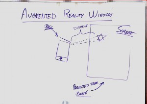
3. Know the Position of an iOS Device in Free Space

Here are a bunch of ways not to get this feature to work (or, at least I couldn’t get this feature working)

  • Accelerometer Data: I first came up with understanding the position in free space by playing with the accelerometer data. However, the accelerometer produces the acceleration. You need to take the double integral of that to find the distance traveled. However, taking the integral twice produces so much noise that it is impossible to calculate accurately. Holding the device perfectly still will say that the device has traveled meters. So centimeter accuracy for any length of time is impossible.
  • IMG_2194Vuforia AR: Vuforia is a great AR framework developed by Qualcomm that has nearly perfect target tracking. The targets/markers can be a photo of any object with well defined (high contrast) boarders. I used this framework before in a UROP, but not for this purpose. The goal was to find the vectors of a particular marker that the projector was projecting on to the screen. Using the camera from the iOS device, it would detect a marker
  • Optical Flow: I believe this one is possible if you have a better understanding of linear algebra. I don’t have very much matrix experience, and couldn’t figure out the math to do this one correctly. It’s probably doable, and someone definitely should do it.

Those three methods all involve the device itself detecting it’s location. After none of these worked, I moved to a fallback: have a secondary, stationary device detect the movement, and wirelessly transfer the data to the moving device. I ended up using OpenCV in OpenFrameworks to detect a marker on screen, and then transfer the location information via OSC back to the iPad itself.

How To Properly Communicate Between Apple Devices

I did not perform on Final Presentations day because I could not get the devices communicating (with ruins part 1 and 3 [and sometimes 2] of my performance).

I initially thought that high level Bluetooth LE protocols would be the way to go, since I’ve used it for iOS to iOS data transfer before. However, when transferring data from iOS to Mac, it doesn’t work. BLE on OS X is only set up to be a central device, not a peripheral. My system needed the Mac to be the peripheral, and the iPad to be the central, receiving device.

OSC saved the day, using the built OSC framework that comes standard on both the iOS and OS X versions of OpenFrameworks.

Midterm Documentation

My midterm project was a visual illusion that takes advantage of the limits of human perception. By creating videos that flash through a deck of shuffled cards showing one frame per card, the typical viewer can’t pick out a single card, which is shown for only 4 milliseconds. A card shown for 2-3 frames is visible by some viewers, and 4 frames is sufficient to be seen by the majority of viewers.

This trick is inspired by a trick popularized in the movie Now You See Me, featuring Jesse Eisenberg. Here is a clip of him performing the trick in the movie.

I experimented with many possible variants of the video to ensure that the video seemed smooth and homogeneous, while still maintaining a high success rate for the illusion. This involved showing the desired card for various numbers of frames and experimenting with blur to make the non-target cards less easily detected.

The video from Now You See Me had extreme blurring on all cards except the 7 of Diamonds, which was fine considering the dynamic action of riffling through cards. Because my video simply showed pictures of cards, there was no believable reason why cards in the middle of the video should be heavily blurred.

My final video involved a combination of longer exposure to the target card and blurring of non-target cards. The cards became steadily more blurred over the first half-second of the video, from zero blur to a 16 pixel Gaussian blur. About two thirds of the way through the video, my desired card was shown for four frames. The first and fourth frames were blurred (20px Gaussian), and the middle two frames were entirely unblurred. This allowed for clear viewing of the card for two full frames. This also still gave the impression that the scene was constantly shifting, as the jump from the blurred card to the unblurred card was mistaken for a jump to a completely different card. In contrast, simply showing the desired card for four frames was always recognized as a “blip” in the video by viewers.

To add the “Inception” component of the trick, I had to find a way to tell the computer which card to force a card on the spectator. I made an mp4 video for each non-face heart card (in addition to the seven of diamonds). By embedding the video into a webpage I was able to process keyboard inputs via JavaScript. On this page where I embedded the video, pressing a number 1-9 (let’s call it x) on the keyboard automatically changes the video src tag to show the video with the x of Diamonds as the target. This enables me to take a card suggestion from the audience (using a plant to guarantee a heart card) then force that card on the user.

I Final Cut Pro for all the editing, because iMovie doesn’t enable frame-by-frame editing. I downloaded a Zip of the card images from http://www.jfitz.com/cards/.

Here is the video of the final trick performed (courtesy of Jon Bobrow).

Midterm Documentation (Robyn Lesh)

Presentation Concept

Marco Tempest-esk presentation combining humor and effects to point out the beauty color gives to this world.

{Presentation Video}   The Magic of Color Presentation

Project Mission

A presentation that points out that color is more than simply a science of numbers and convoluted terms but rather the existence of color makes our world the wonderfulness that we perceive.

Dull & dreary to gorgeously beautiful.

Ex)

RedMountainB&W to RedMountain

and

YellowFlowerB&W to YellowFlower

Project Description 

Two guest lecturers, Professor Winberg and Professor Landers (tribute to the horrible & excellent Introduction to Biology professor pair, Wineberg & Lander) give a presentation on “Color as We See It”. Winberg befuddles the audience with a decisively unnecessary use of excessively long words and other absurdities of speech including details on what will not be covered and the importance of understanding minuscule details rather than the idea as a whole. Landers then takes the scene and shows why color is an amazing thing in our world, that provides life and vitality in its simple existence.

With color, the dull becomes interesting, the usual becomes beautiful and our world, magical.

{Powerpoint Video}   The Magic of Color Midterm Slides


Preliminary Idea and Evolution

The initial idea with my Midterm presentation was to expand on my Trick++ which was based on the idea of an abrasive professor character with a finicky presentation that acts up against my will. I was very excited the response to my Trick++ character and excited for the directions I could take the personality I had invented.

However when I tried to write actual content for the extension of the character in my Midterm presentation I ran into a wall in that I couldn’t think of any explanation for WHY my powerpoint would be acting up behind me. This lack of a practical explanation drove me away from the crazy professor persona and left me in need of a presentation topic.

Idea Potentials

TED talk-like
sailing
colors (history of?)
my life
crazy/weird teaching/guest lecturer

Possible Technological Components

Face recognition component
(Color changing?)
Reveal in pre-sent email
Reveal on website
Class color know-er

Unused Coding Sketches (can include code on request?)

SendEmail
Play Video
Input GUI

Current Plan for Final

Return to the abrasive hard-nosed professor character persona and absurdly changing slides. =) The cheeky, misbehaving slides will be the fault of a TA who is finally getting back at the mean unfriendly and unpopular prof. Initial idea-generating phrase, the professor’s area of expertise will be her downfall? Or just absurdity.