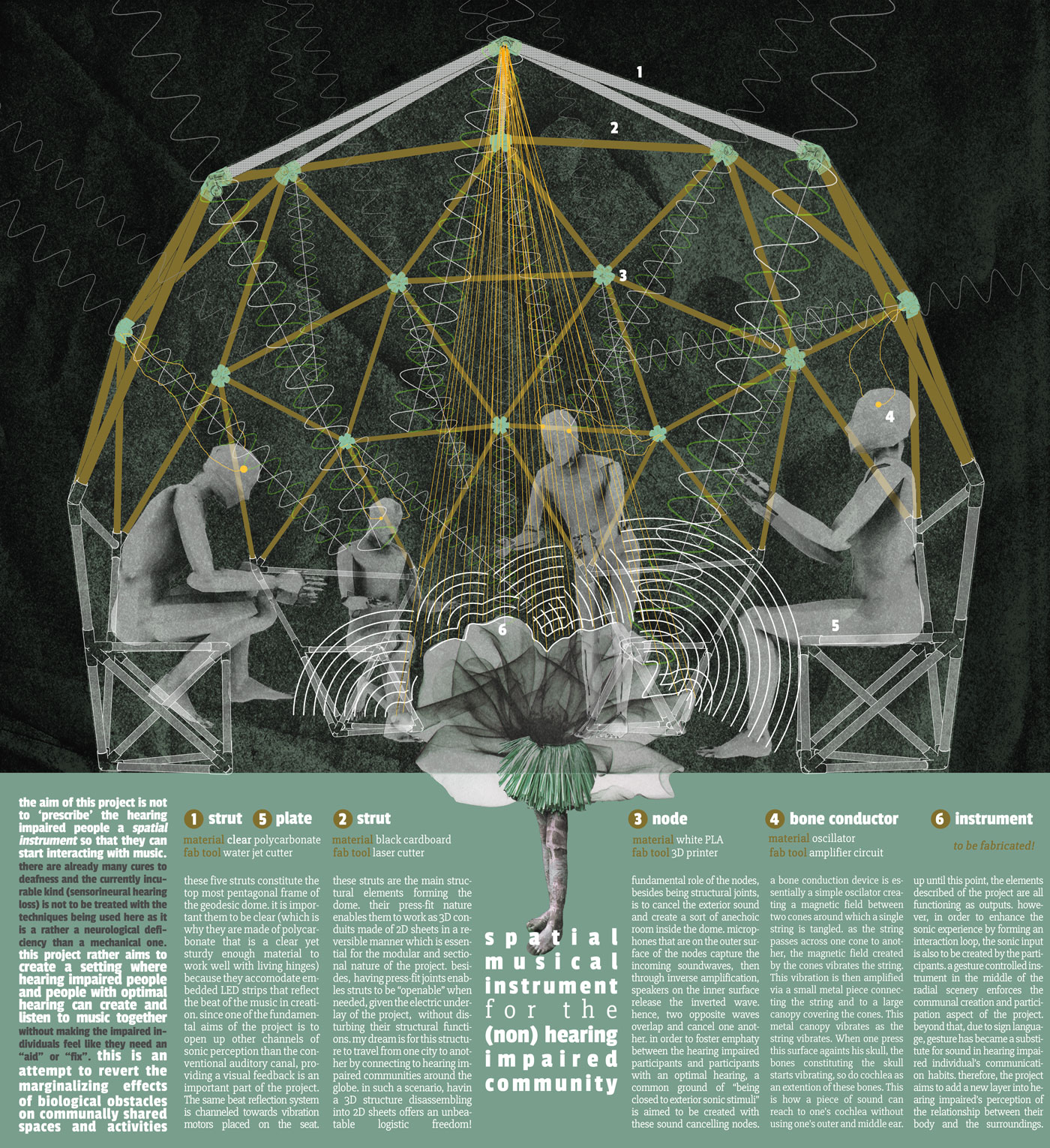
The aim of this project is not to ‘prescribe’ hearing impaired people a spatial instrument so that they can start interacting with music. There are already many cures to deafness and the currently incurable kind (sensorineural hearing loss) is not to be treated with the techniques being used in this project as it is a rather a neurological deficiency than a mechanical one. This project rather aims to create a setting where hearing impaired people and people with optimal hearing can generate and listen to music together without having the impaired individuals feeling like they need an “aid” or “fix” to fully be a part of a musical context. This is eventually an attempt to revert the marginalizing effects of biological obstacles on communally shared spaces and activities

Sci-fi inspiration: J G Ballard, Sound Sweep
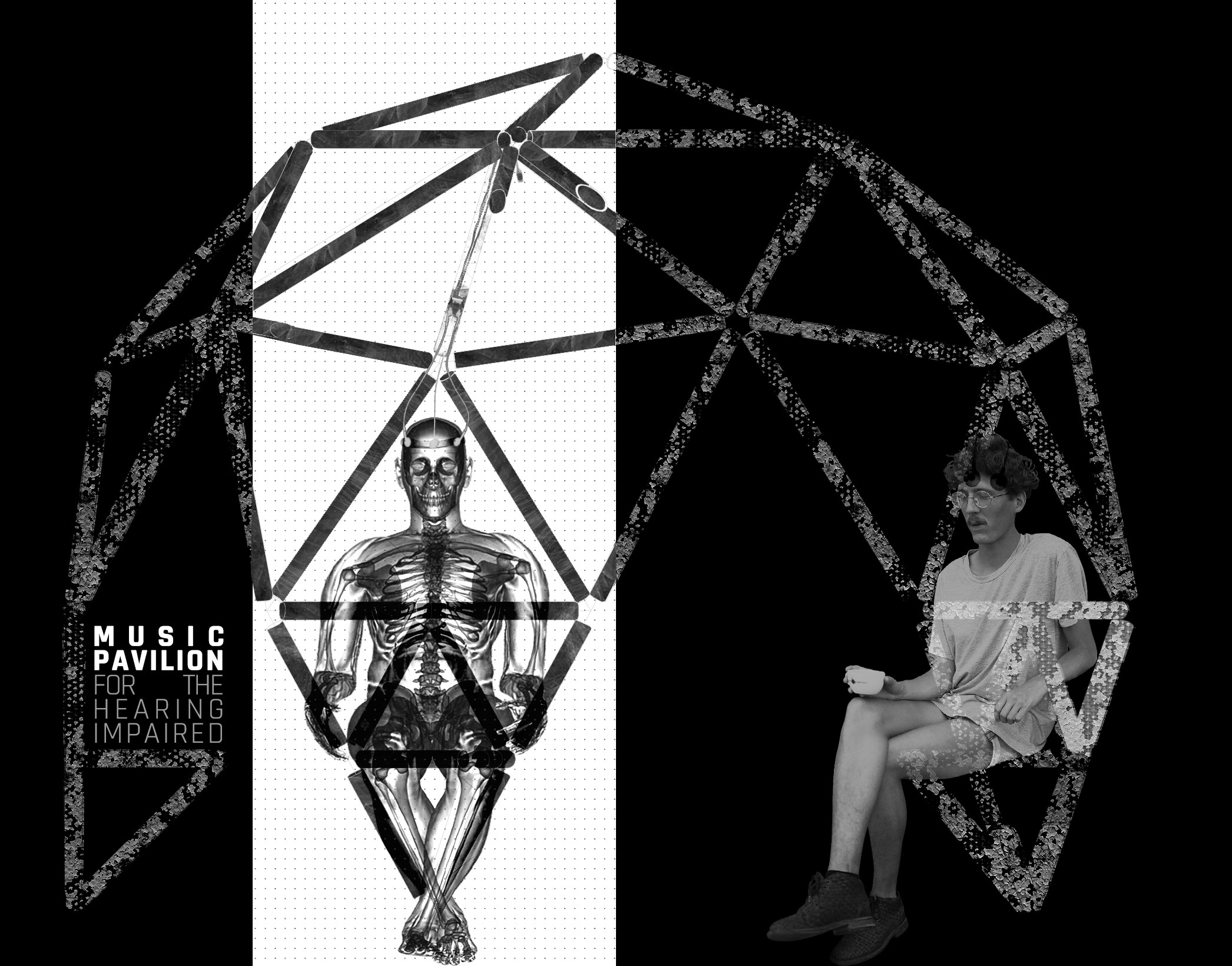
My departure point was J G Ballard’s science fiction story Soundsweep where, due to the noise pollution in a distant future, contemporary musicians start shifting the sound range within which they compose into an ultrasonic level. Therefore, since there are not any audible music left; sound, once created, does not leave any residues behind. In this future society, where everybody seemingly listen to this “ultrasonic” music and enjoy it, nobody practically hear anything. This scenery inspired me to design a musical setting where the actors are seen as practically listening to nothing ,with their open ears, yet do react to music that is being played literally inside their heads through bone conduction!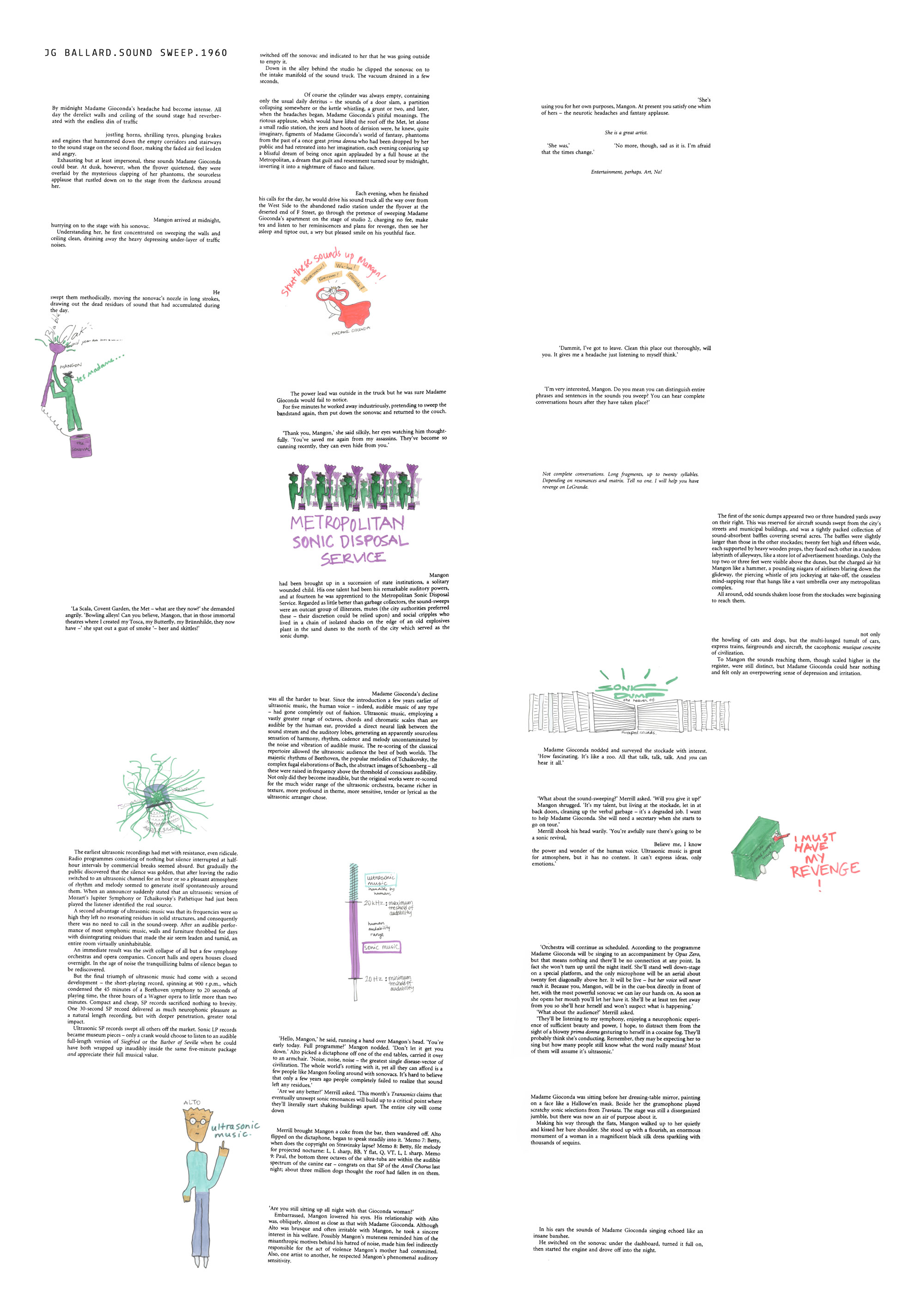
Above, you can find some excerpts from J G Ballard’s science fiction story “Sound Sweep” with my illustrations. And here, you can view a more interactive narration of the story.
On the other hand, in an era where huge efforts are in the making for the democratization of musical creation and accessibility, it seems unfair to see hearing impaired individuals being a part of the communal aspect of music at a very restricted level. With today’s technology, we are able to cure most hearing deficincies, and the ones that are currently incurable (most kinds of sensorineural hearing loss) are being profoundly studied. Therefore, it is not the medical effort but the designer’s will what seems what is missing in enlarging hearing impaired’s social comfort zone today. The question I want to ask with this statement is: what can we do to create more inclusive spaces not only for those who are experiencing biological hardnesses (this is still a type of “pozitive” marginalization in fact) but to arrive to a level where these “impariment” implications are no longer relevant. In the search for an answer to this question, I decided to create a spatial music instrument to be played collectively by both hearing impaired individuals and individuals with optimal hearing.
To provide a bit background on the anatomic underlays of the hearing impariment, we can broadly state that there are mainly 2 kinds of hearing impairement: sensorineural hearing loss and conductive hearing loss. Today, if you are a hearing impaired individual and if your doctor is telling you that there is nothing the medical world can do, then you are most likely to have a sensorineural hearing loss which stems from deficiencies regarding the neural pathway of the audial perception. Contrarily, the conductive hearing loss occurs due to mechanical problems in the structure of the ear itself; before the soundwave captured by pinea reach cochlea and get transformed into a neural signal through the hair cells covering cochlea. In this type of hearing loss, as the problem is between cochlea and outer ear, bone conduction based hearing implants can be of solution since they directly excite the cochlea by by-passing the outer and the middle ear. If problem is in cochlea itself generally the deficiency can be resolved by cochlear implants.
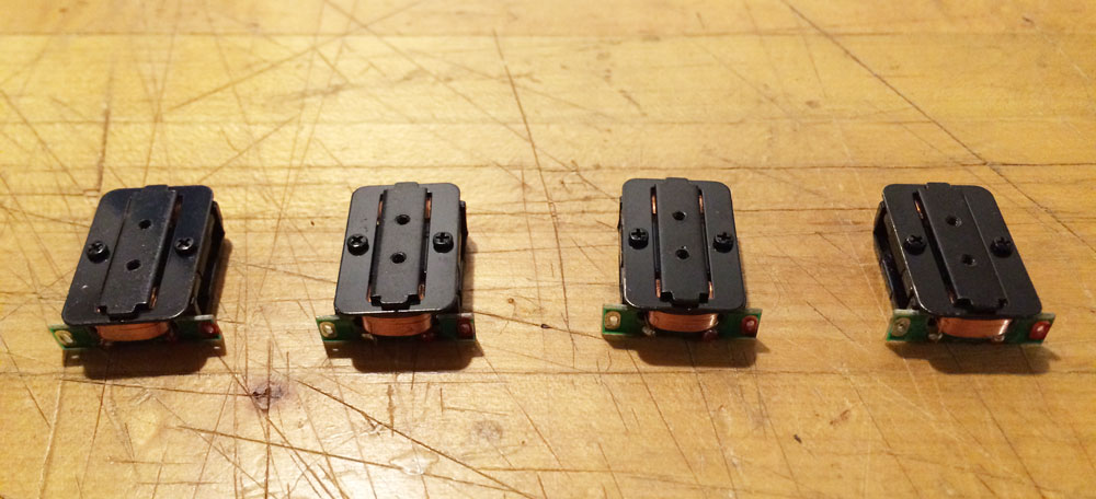
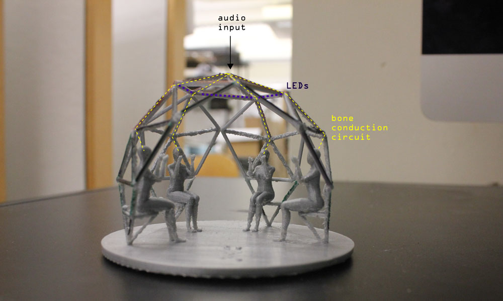
In my project, I use a simple oscilator creating a magnetic field between two cones around which a string is tangled. As the string pass across cones, the change in magnetic field vibrates the string. This vibration is them amplified via a small metal piece connecting the string and to a large canopy covering cones. This metal canopy vibrates as the string vibrates. When one press this surface againts his skull, the bones constituting the skull starts vibrating, so do cochlea as an extention of these bones. This is how a piece of sound can reach to one’s cochlea without using one’s outer and middle ear.
Overall, since the project altogether was more ambitious than what is required by How to Make Almost Anything’s final project which is a demonstration of the combination of different skills learned during the course (hopefully in an interesting way), I decided to break the project into sub goals:
- 1.design and build the dome
- 2.design and build a bone conduction circuit that is embedded inside the dome
- 3.design and build a LED circuit that flashes according to the beat of the audio
- 4.design and build a vibration motor circuit that responds to the beat of the audio
- 5.eventually, instead of using an audio file, design a gesture-based instrument so that the hearing impaired users can also produce the music itself other than just listening to it.
I aimed to complete the first 4 steps in the framework of this course, yet despite my efforts on trying to understand the way H-bridge works, I managed to do only the first 3. More on the process is below:
EXTENSIVE DOCUMENTATION OF THE FABRICATION PROCESS:
Part1_Fabricating the elements for the geodesic dome structure
A.Dome’s base
step1: Buying the metal tubes
I decided to use metal tubes for the base of the dome because this is where the vibration motors were going to be placed and steel is great to intensify vibration! I bought 10 of this EMT conduit from home depot; total cost was around $35.
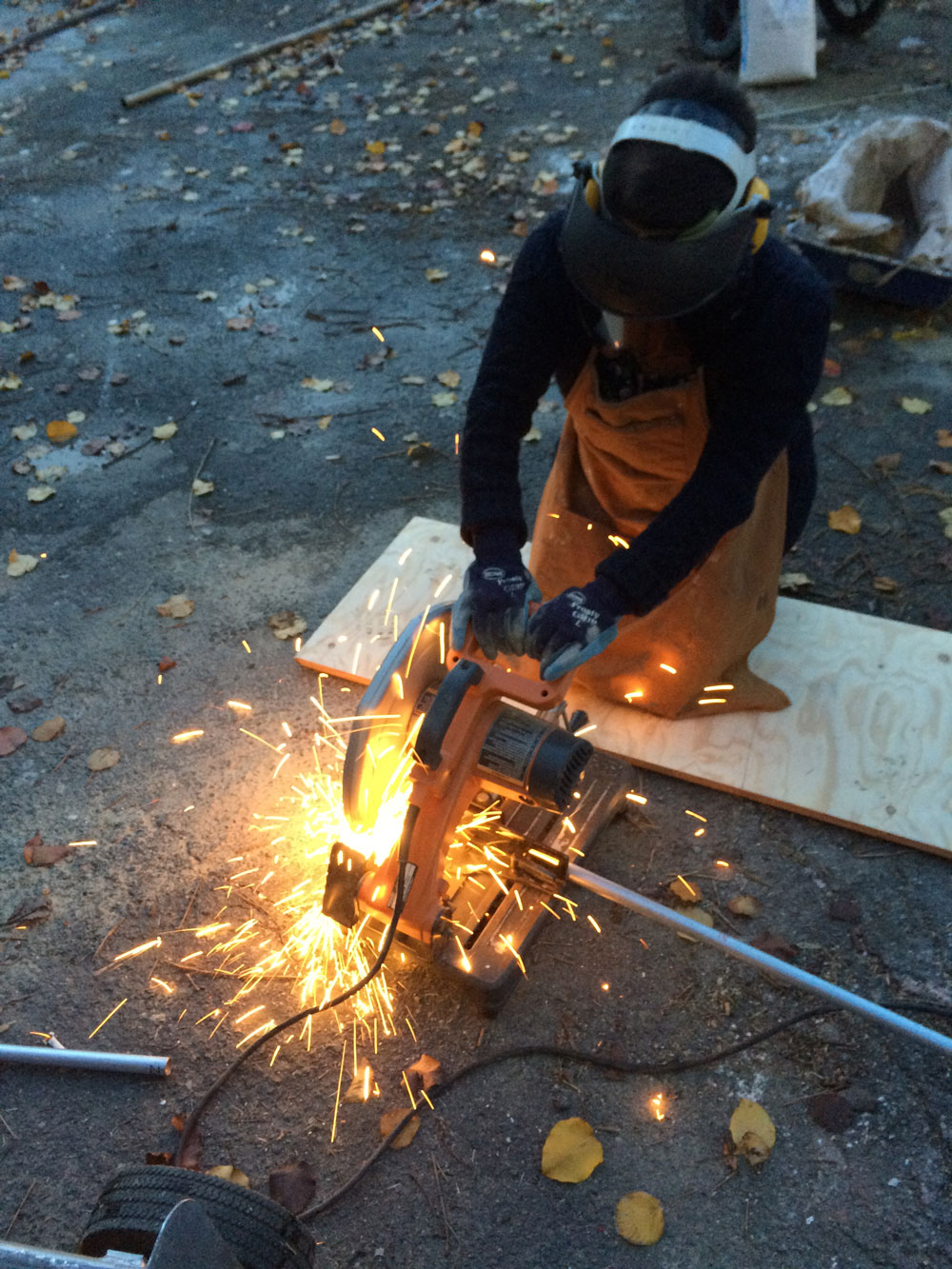
step2: Cutting the metal tubes
I used the metal chop saw for cutting the tubes into the dimensions I needed in N-51
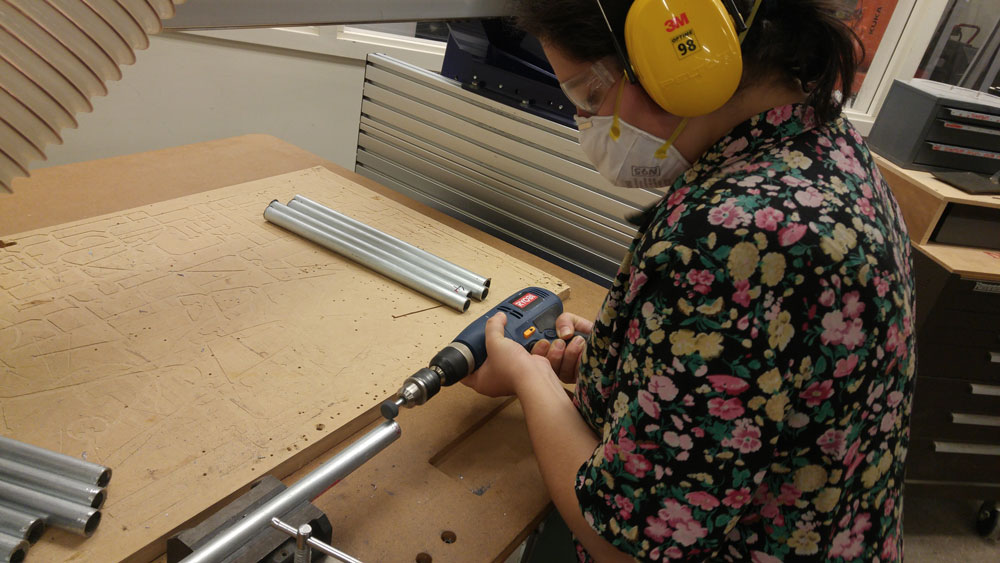
step3: Grinding the edges of the metal tubes
After cutting the metal tubes, the ends needed grinding.
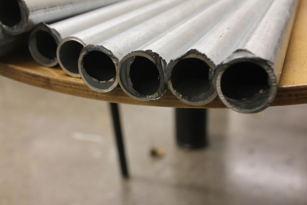
For half of the tubes, I used metal grinder at N51, and for the rest, used the drilling machine with a grinder end.
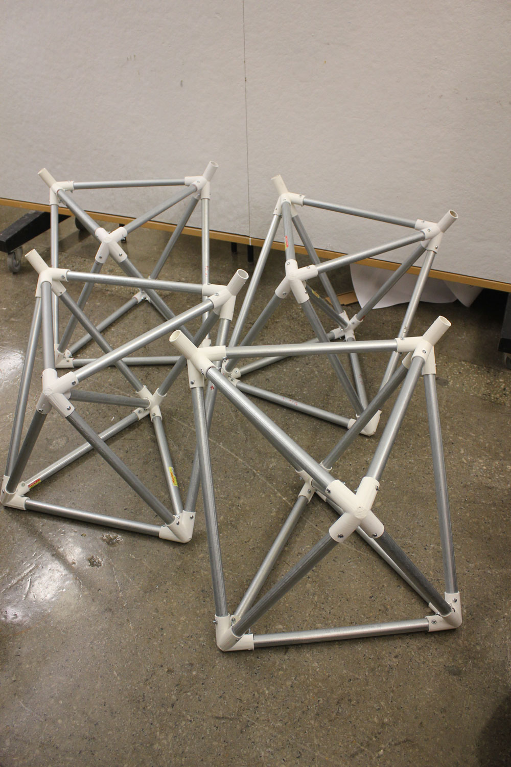
step4: Bringing the tubes together to create the sitting elements of the dome
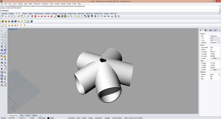
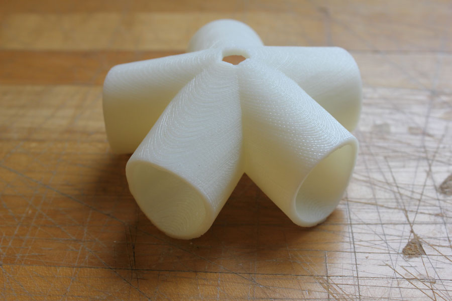
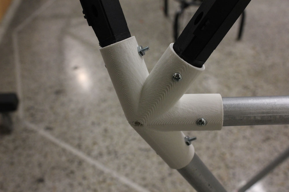
I had previously 3D printed the nodes:
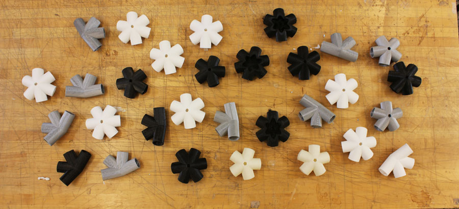
Assembling the tubes with nodes:
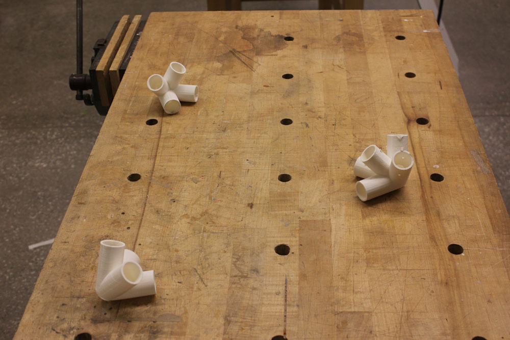
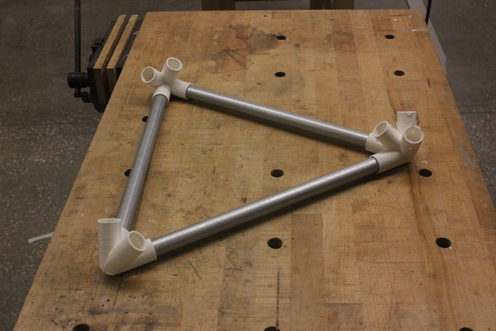
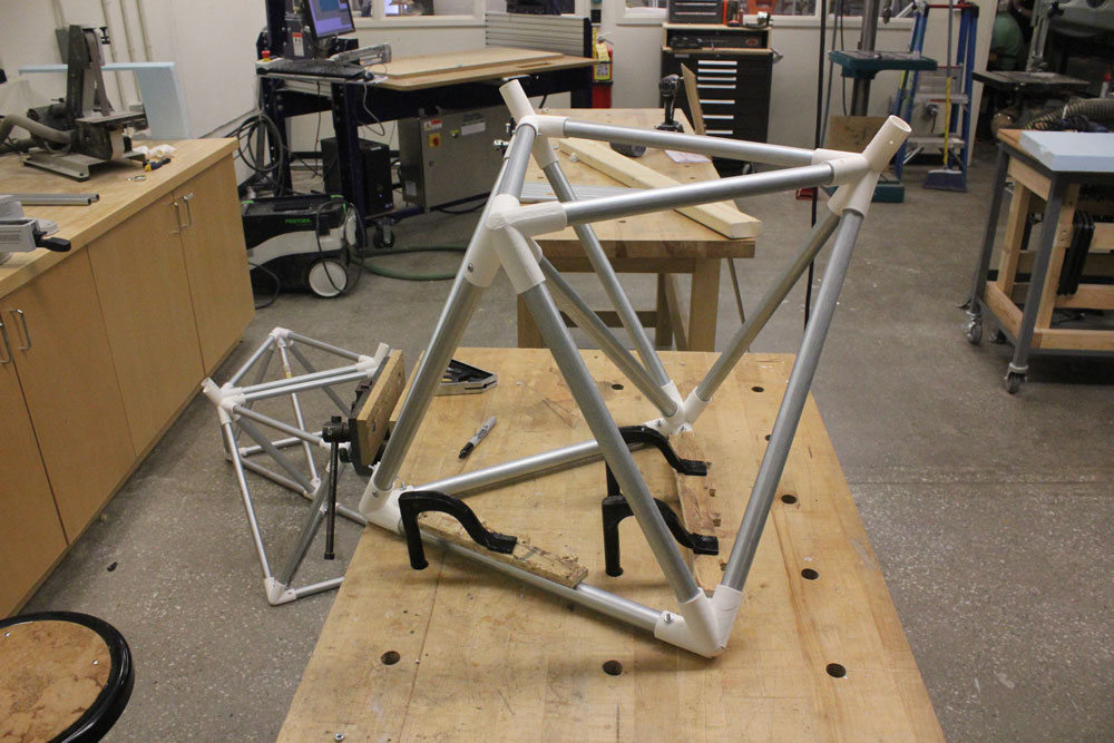
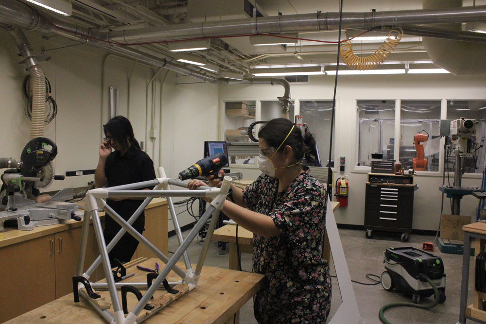

et voila!
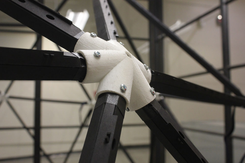
B. Dome’s struts
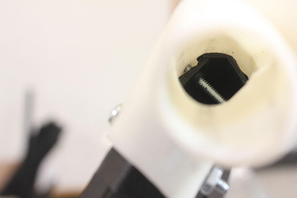
Struts are the main structural elements forming the dome. Their press-fit nature enables them to work as 3D conduits made of 2D sheets in a reversible manner which is essential for the modular and sectional nature of the project. besides, having press-fit joints enables struts to be “openable” when needed, given the electric underlay of the project, without disturbing their structural functions. My dream is for this structure to travel from one city to another by connecting to hearing impaired communities around the globe. In such a scenario, havin a 3D structure disassembling into 2D sheets offers an unbeatable logistic freedom!
step1: Buying the materials for struts
I decided to use 2 differet kind of material for the struts. One is a black museum board from Blick and the other one is a polycarbonate sheet from McMasterCarr. I bought approximately 10 black museum board (cost around $100) and 4 polycarbonate sheet (2 of 24×24″ + 2 of 24×48″; total cost of 4 boards were around $70).
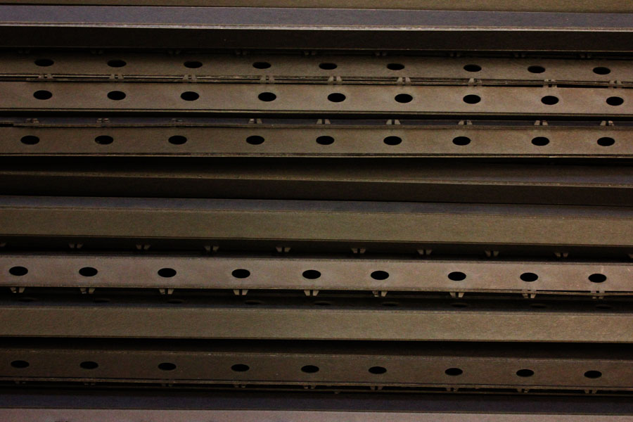
step2: Making the cardboard press-fit struts
The press fit struts were to be made by cutting & scoring (with a laser cutter) then folding a black museum board. Therefore I started experimenting with different notch designs and scoring frequencies:
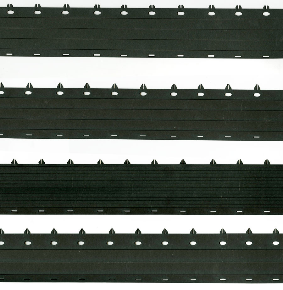
After deciding on the optimal design, since the frequency of my geodesic dome was 2, I only had to fabricate two different type of struts with different lenghts.
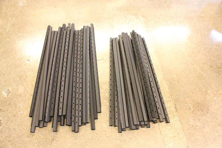
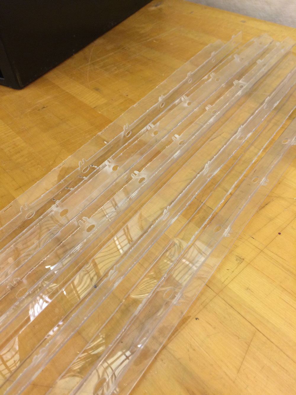
step3: Making the polycarbonate press-fit struts
the main reason why I wanted to make some of the struts with polycarbonate (which is clear yet not brittle as acrylic and not non-structural like polyprophelyn or acetat) is to stick some LED circuitry into its surface with vinyl cutter. However with polycarbonate, since it’s not possible to use the laser cutter due to the material’s release of toxic smoke, the process was more tricky than it was with cardboard. I was only able to use waterjet cutter for this material with which the concept of scoring doesn’t exist.
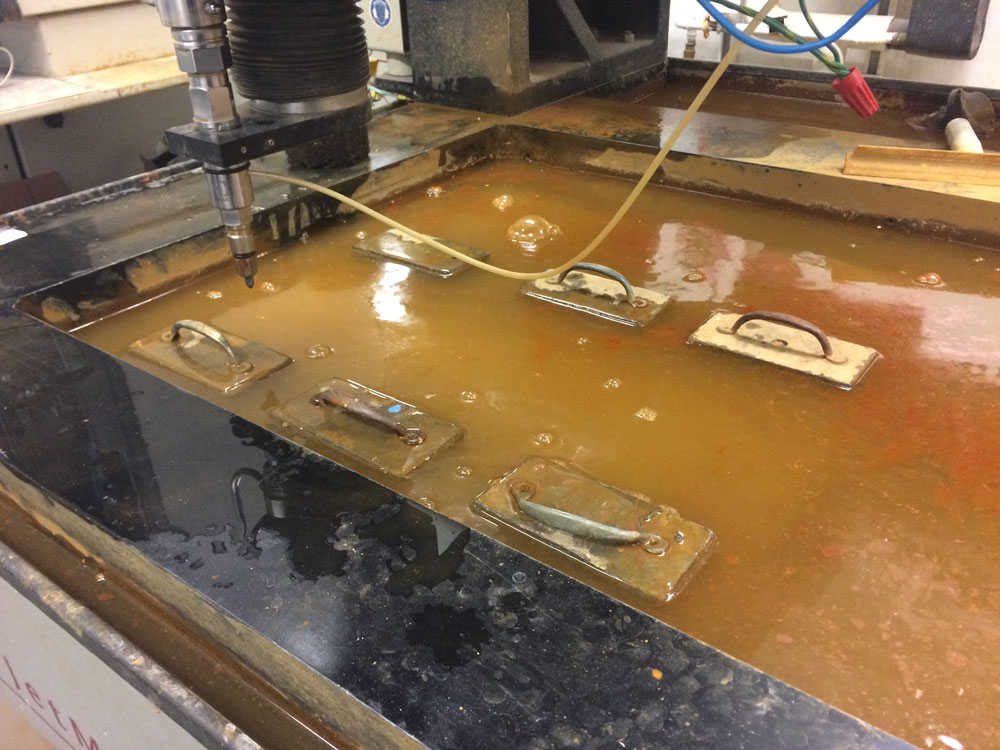
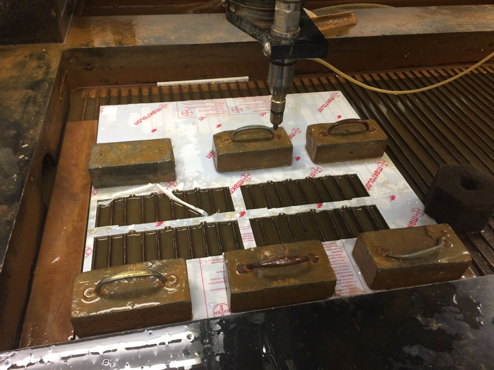
step4: Waterjet cutting the polycarbonate sheets
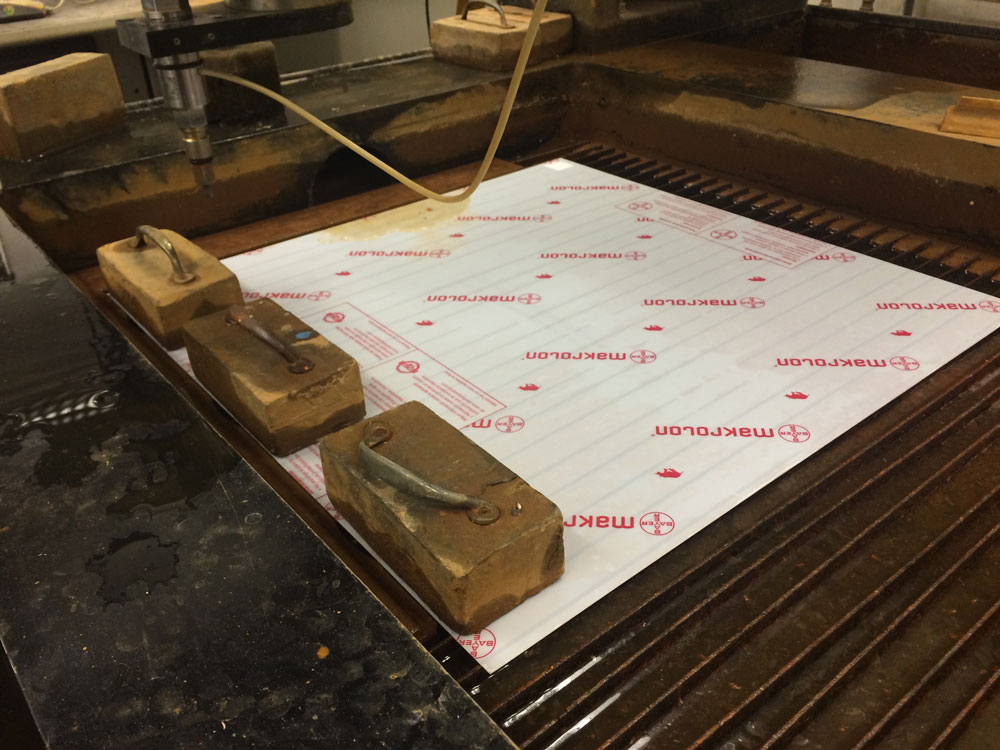
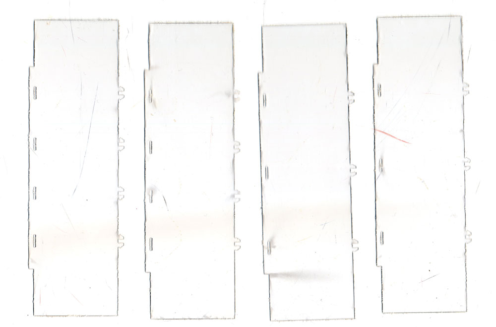
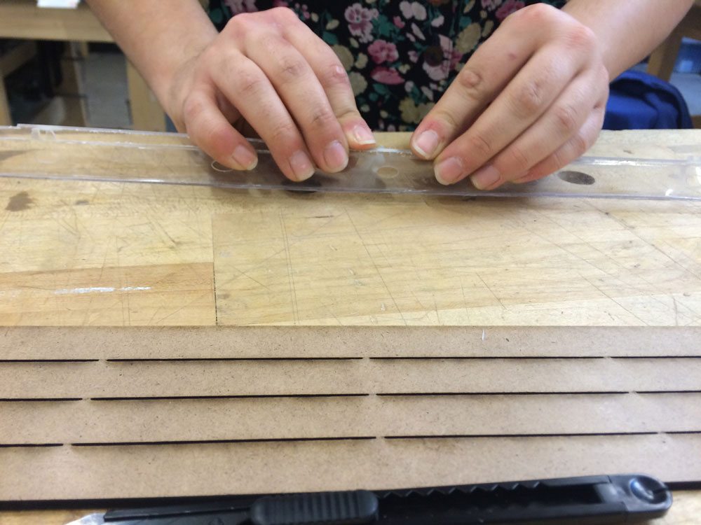
step5: Scoring the pieces manually by using a mask, cutter and hot air gun
So, I designed and lasercut a mask which helped me score the pieces neatly by hand.
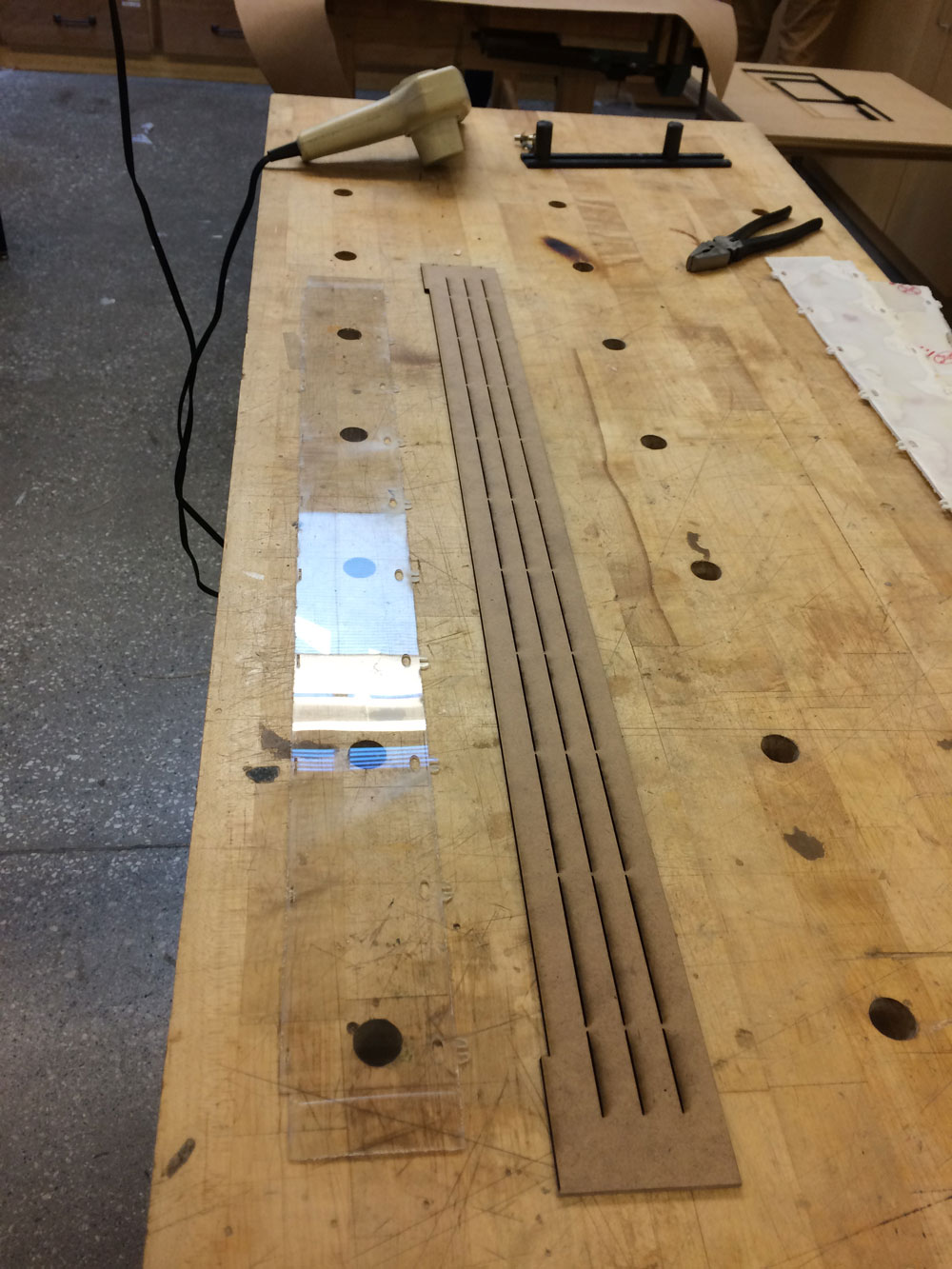
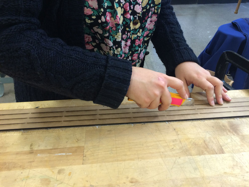
after placing the mask on top of the waterjet cut polycarbonate piece, I clamped them to the desk to prevent layers from sliding.
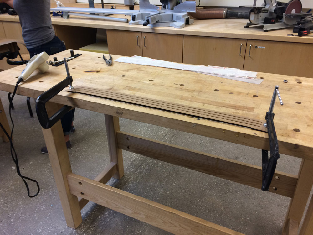
then scored the polycarbonate carefully with a cutter. The mask helped me make sure that the lines were perfectly straight!
then, by applying heat to the fold lines, I increased the material’s elasticity which helped me fold it easily.
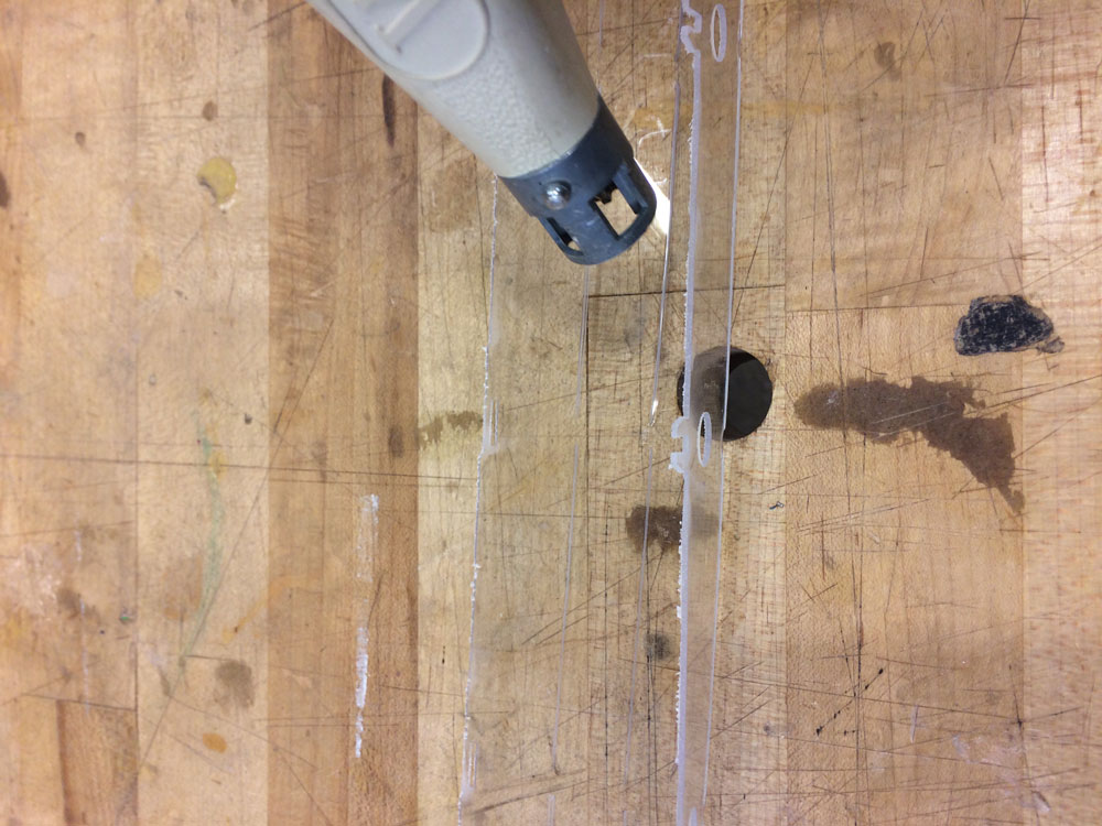
et voila!
Part2_Producing the electronics of the dome
A. Bone conduction
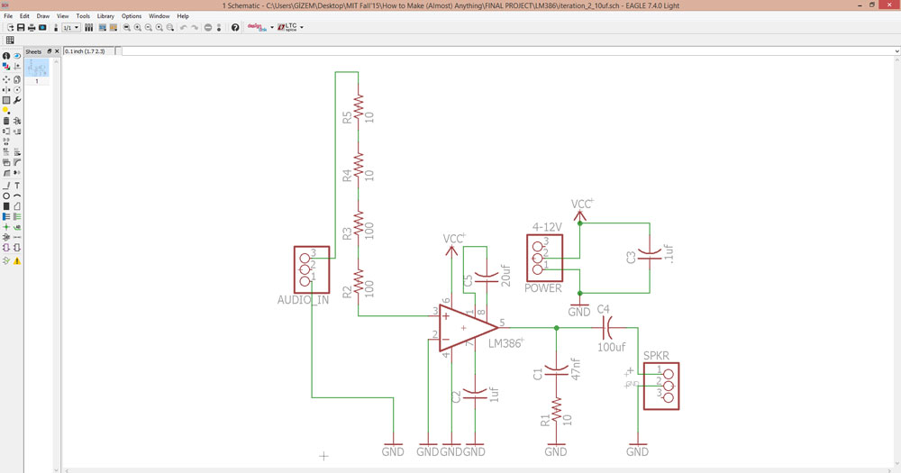
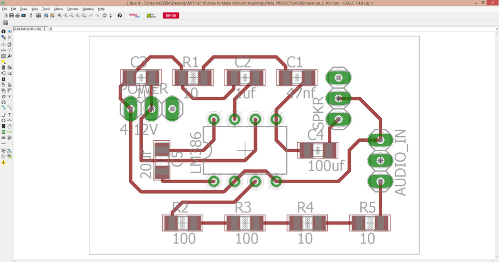
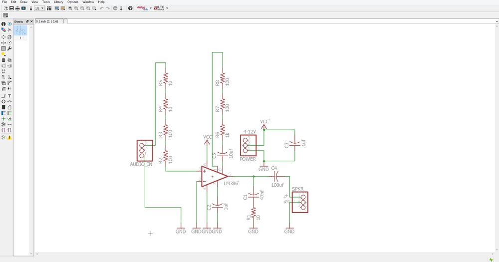
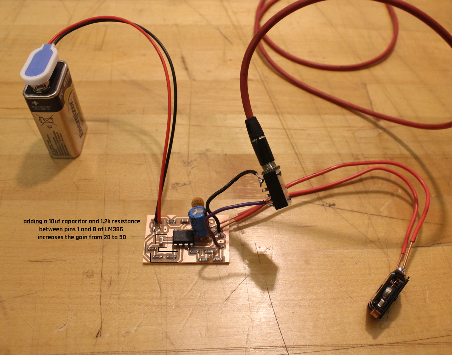
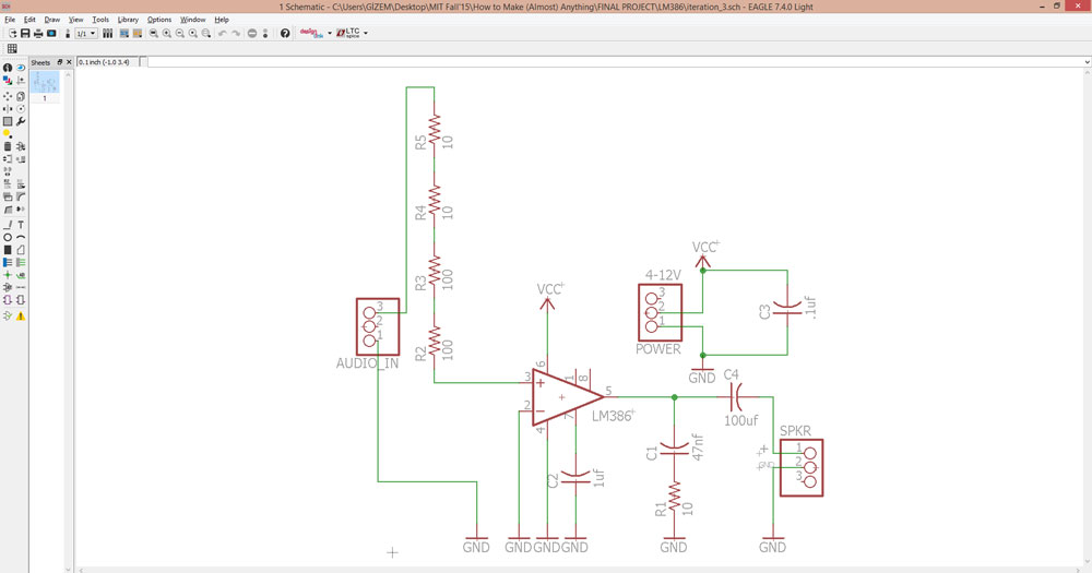
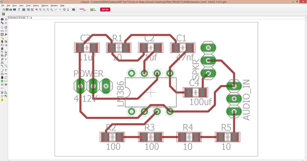
step 1: Deciding on the amplifier’s gain
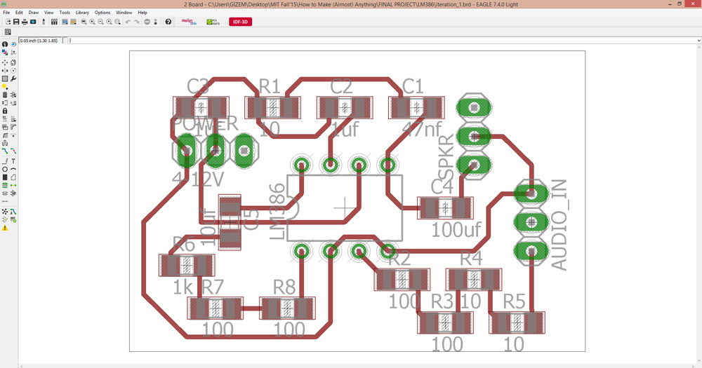
I made 3 different iterations (gain:20, gain:50, gain:200) of my amplification board for bone conduction circuit. Used the datasheet for LM386:
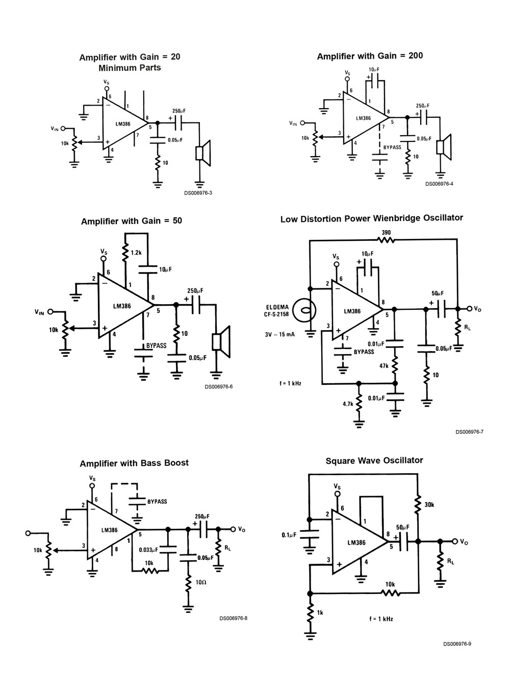
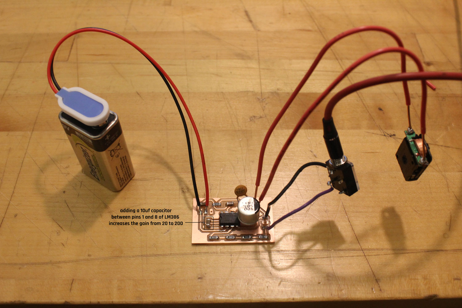
gain 200
I connected a capacitor (20uf) between the pins 1 and 8 of the chip (LM386)
gain 50
I connected a capacitor (20uf) and a resistor(1.2 k ohm) between the pins 1 and 8 of the chip (LM386)
gain 20
pins 1 and 8 of the chip are disconnected
Finally, I decided on using the gain:20 one since the sound was the most clear in this circuit.
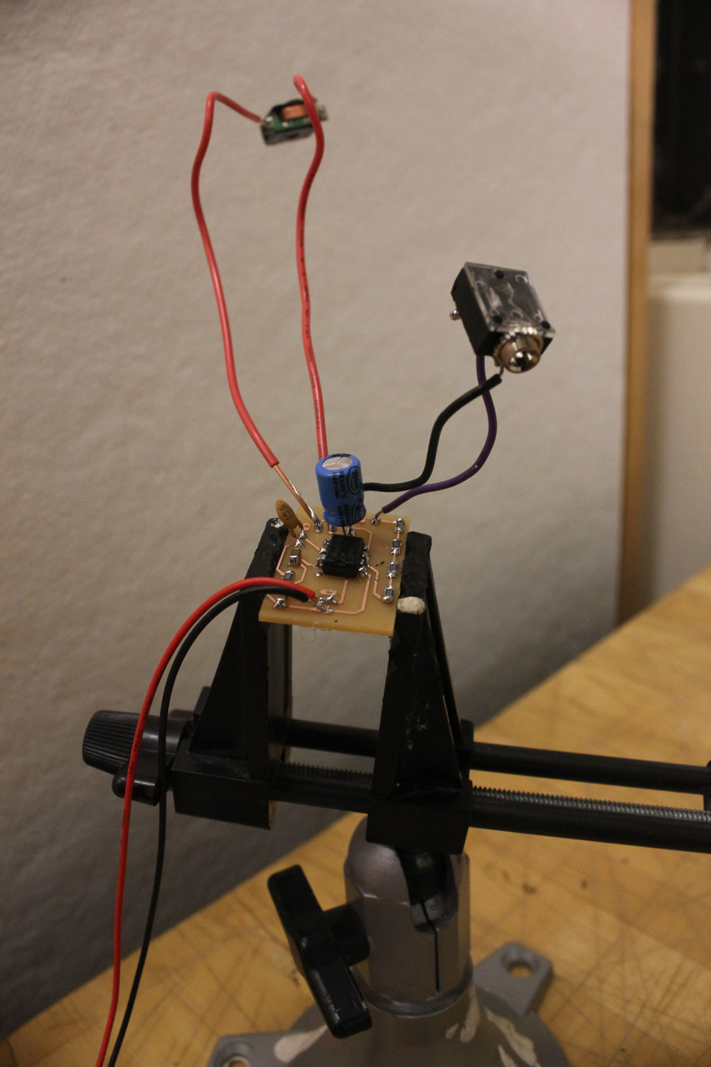
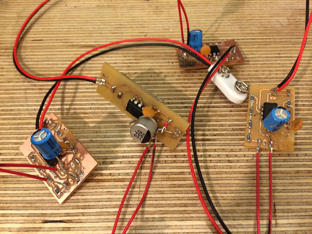
step 2: Fabricating 4 amplifier circuits
B. Beat reflective lights embedded on a clear strut
after vibrating the skull to create the sound within ones cochlea, I wanted to have a visual feedback as well as a tactile one. For the latter, I would need a vibration motor circuit and I decided to postpone it for future updates of this project since simply there was not enough time. However I decided to try the former.
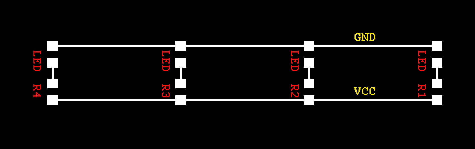
step 1: Design & fabricate a small section of a LED strip for the proof of concept
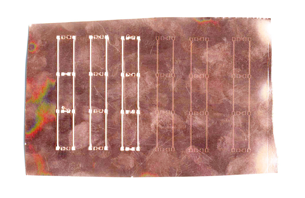
homemade LED strip trace:
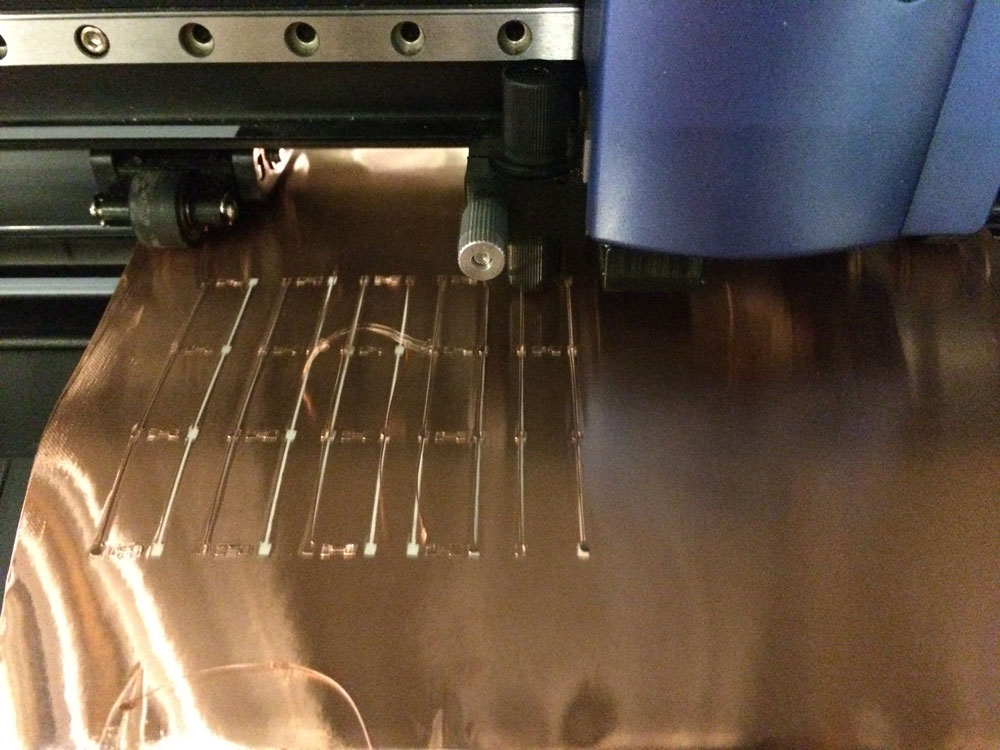
tracing copper sheets with vinyl cutter, trying different force intensities:
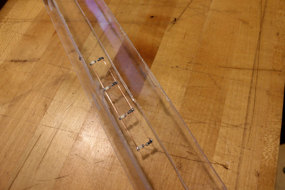
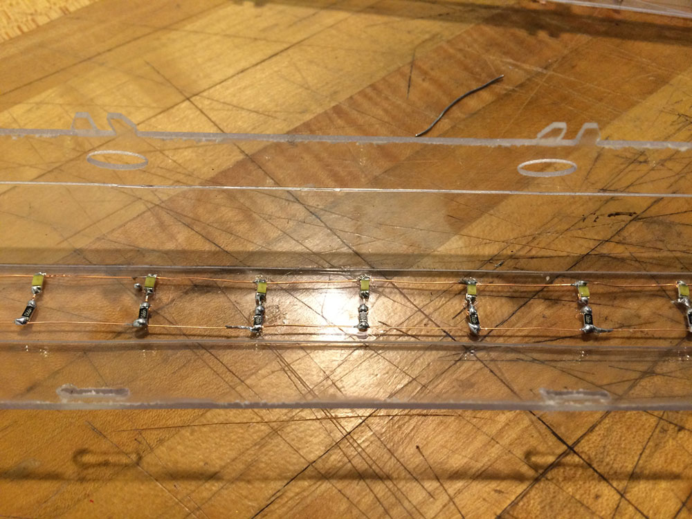
sticking them into a polycarbonate strut’s surface and populating the circuit with LEDs and resistors:
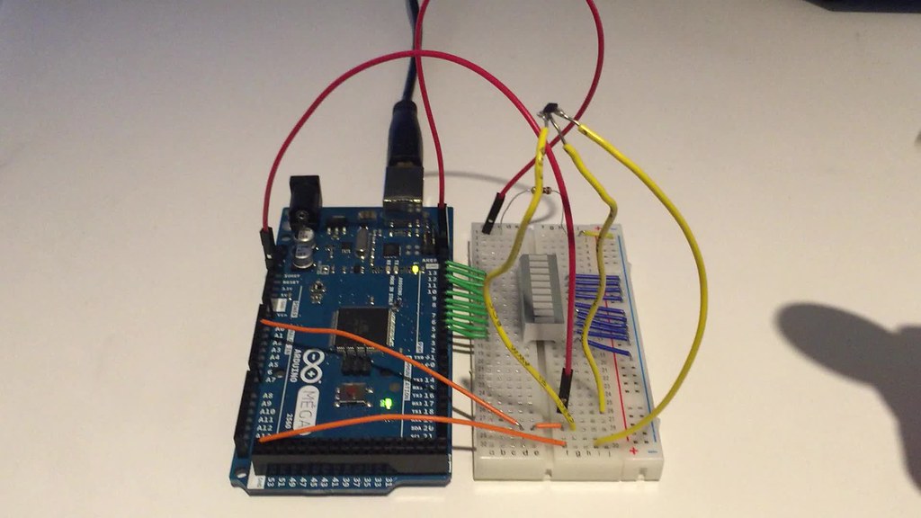
step 2: Connect the circuit to the beat detection system (arduino + processing)
Having made my own circuit for the core electronic part that was bone conduction, I decided to use an arduino duemilanove that I made during input devices week for the light addition. The programming environment was Arduino IDE and Processing (through running the standard firmata). I basically used the adapted version of my code from the interface programming week for beat detection on processing.
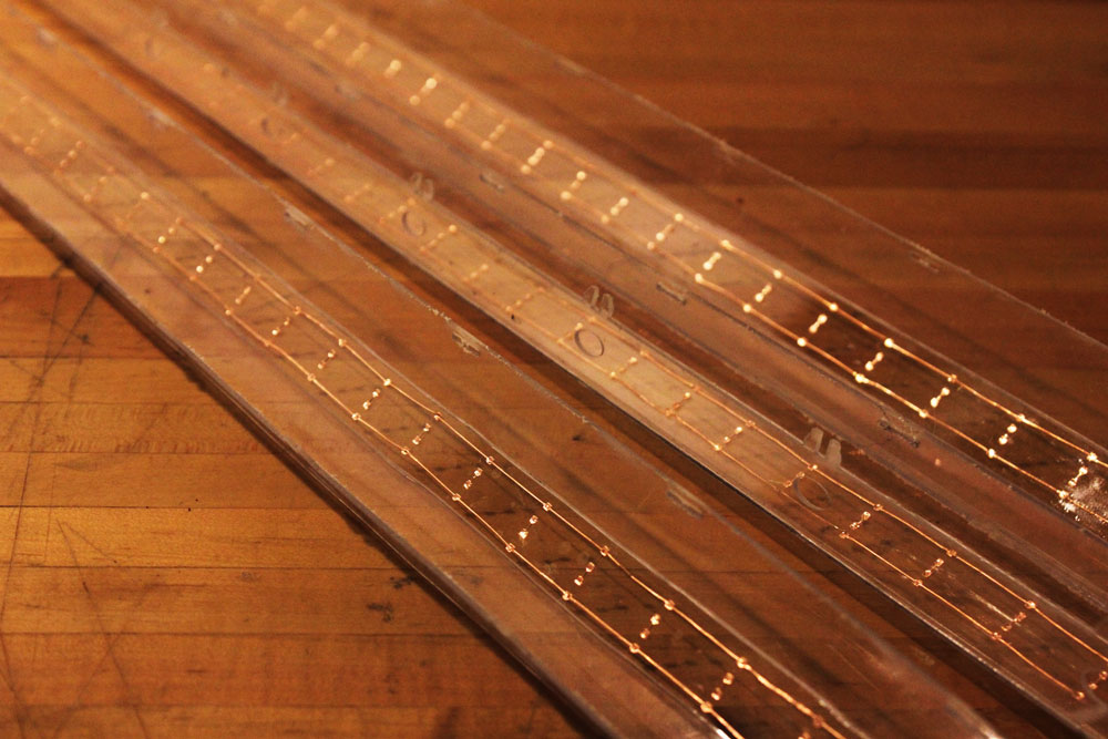
step 3: Actually fabricating 3 homemade LED strip embedded clear polycarbonate struts
After successing in the “proof of concept”, I decided to fabricate LED homemade LED strips for the lenght of at least 3 polycarbonate struts since I was separating the beats into 3 channels thru Processing. The main reason why I wanted to do my own LED strip by using a ton of LEDs and copper stickers is because I find the commercial LED strips super kitch. So, for the sake of being able to end up with exactly what I wanti I spent painstaking hours for the vinyl cutting of the copper, sticking the copper bands into the polycarbonate surface and soldering the resistors + LEDs into it. Ugh!!!
after vinyl cutting more copper bands, I started placing them onto the struts’ surfaces
then I soldered the resistors and LEDs
all looked pretty good, so I decided to try each strut with the actual beam detection current. Video below is a timelapse of my trouble shooting session
all done! now it was time to snap close the strut and articulate it to the structure!
C. Forehead band: interface between the bone conduction devices and the skull bones
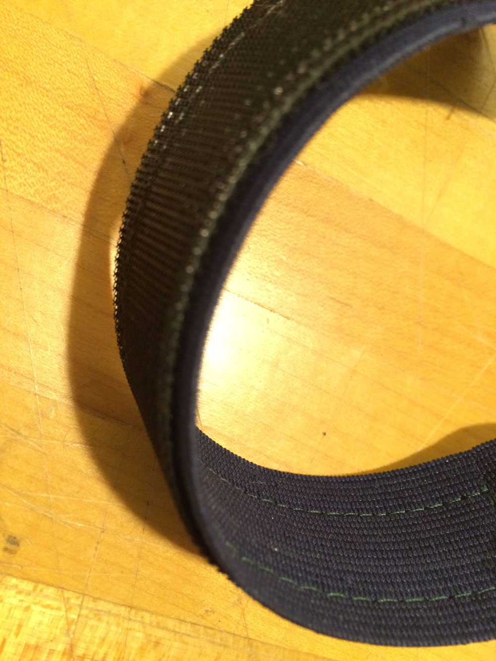
step 1: Sewing velcro into elastic band
I bought 2 rolls of elastic band and a one roll of velcro. After cutting them into desired lenghts by making sure that they will be adjustable to different head diameters, I needed to sew the velcro into the elastic strap.
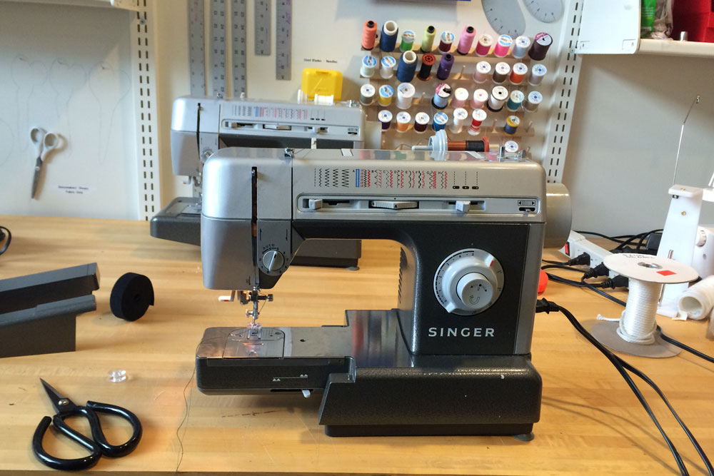
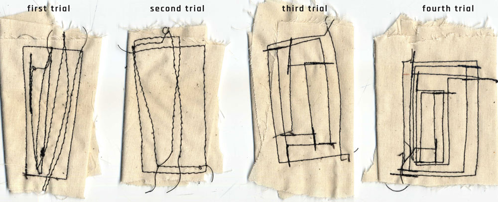
I had never used a sewing machine before but I learned how to use it pretty quickly. I was way faster compare to sewing by hand.Before using velcro and elastic band, I made some trials on a scrap textile.
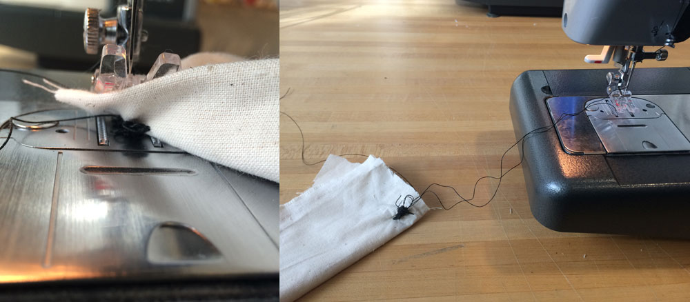
Of, course I got it jammed couple of times but this problem can easily be solved by pulling the mingled thread out of the bobin repository (make sure to higher the needle before to not to break it!)
et voila!
step 2: Sewing bone conduction devices into the forehead band
finally all the velcro bands were sewed into the elastic band. now it was time to sew the bone conduction devices into the head band. I did that by hand since it required lots of attention.
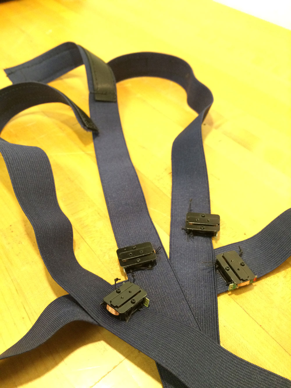
now only thing I had to do was to solder the ground and VCC cables to the bone conduction device during the final assembly of the dome.
et voila!
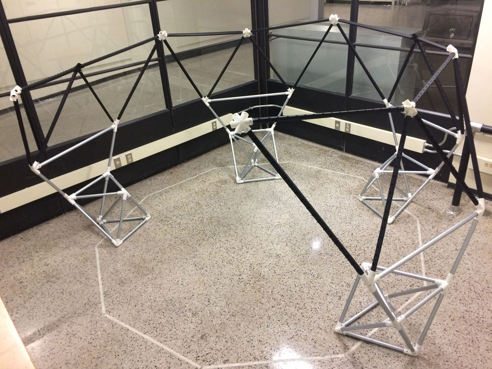
Part3_Final integration and the set up of the dome
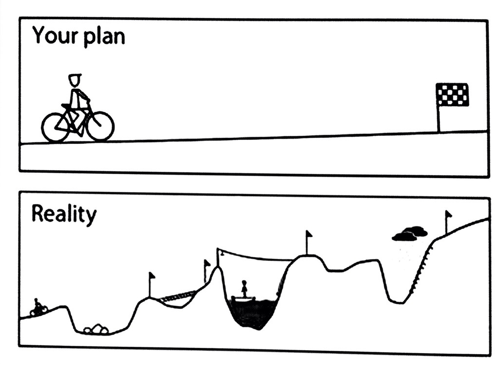
so far, it had been very challenging to come to this final phase. I appreciate to the truth in the illustration below:
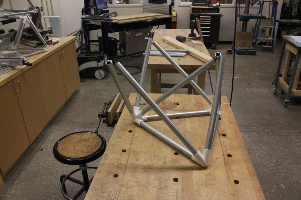
The metal bases of the dome: check!
The black carton and clear polycarbonate struts: check!
Bone conduction amplifiers (4 of them!): check!
Adjustable forehead bands to interface the bone conduction devices to the skull: ckeck!
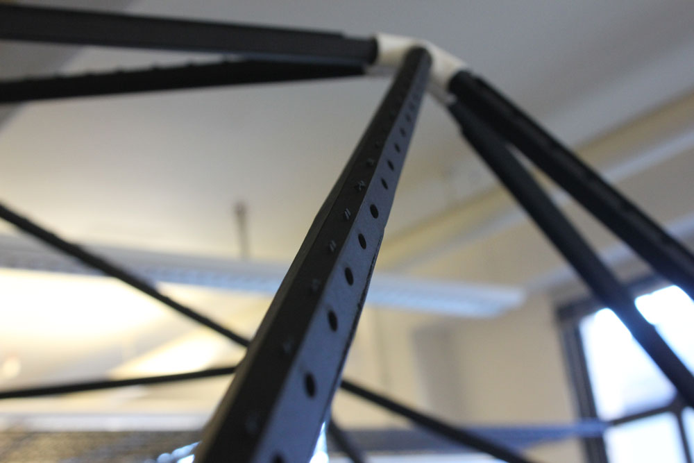
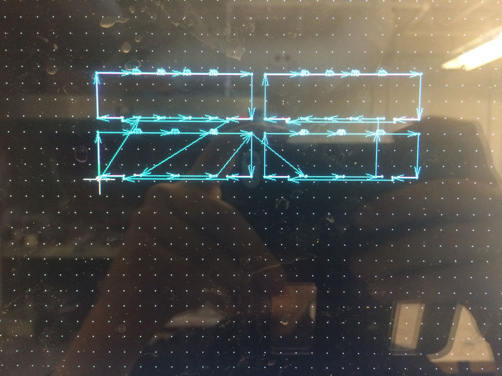
I have started with marking the decagon projection marking the edges of the horizonral struts. This reference is important to be able to know where to put the metal bases.

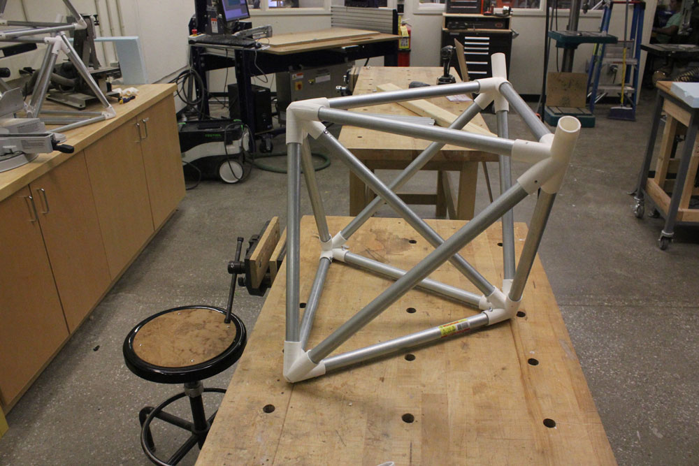
After placing the metal bases, I started articulating the black carton struts to them.
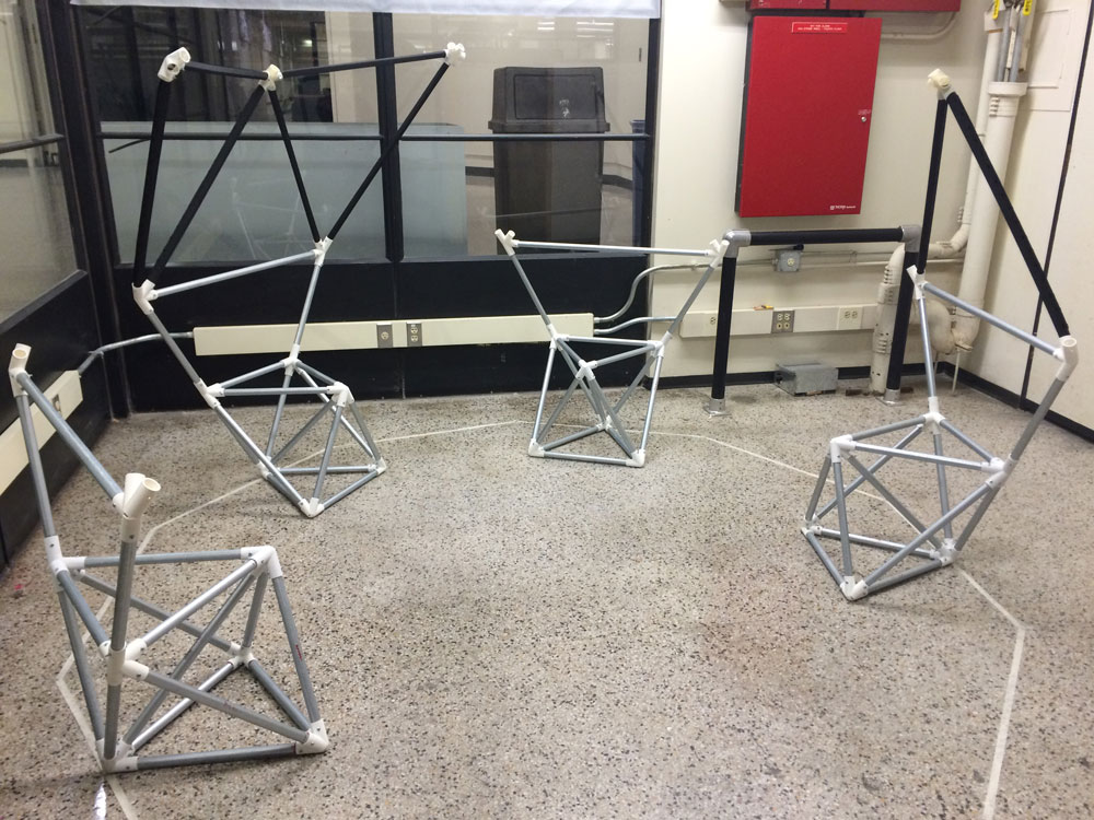
Then articulated the black carton struts to black carton struts.
even though the assebly theoretically looks fairly easy, it actually requires quite an effort since making holes in every branch of the connecting nodes is a painstaking process!
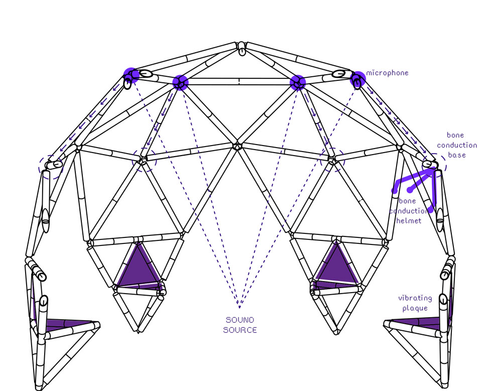
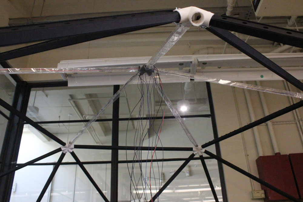
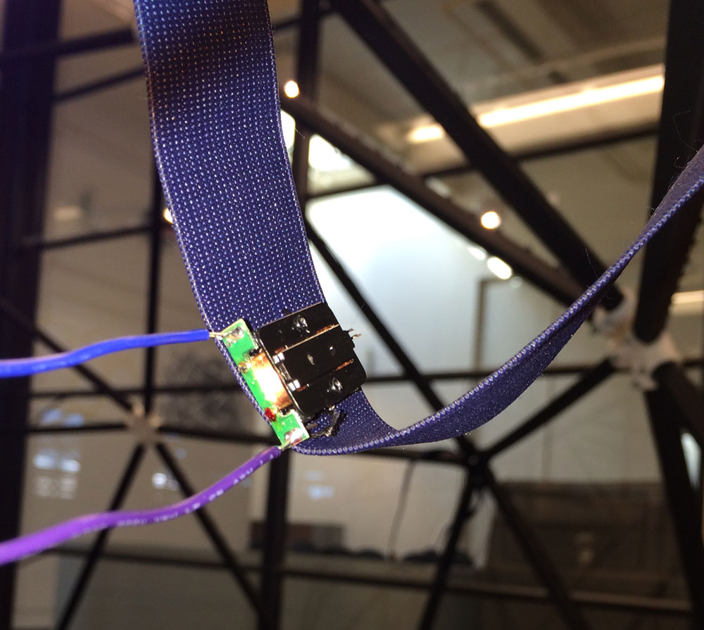
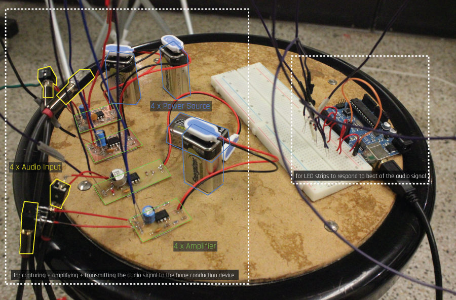
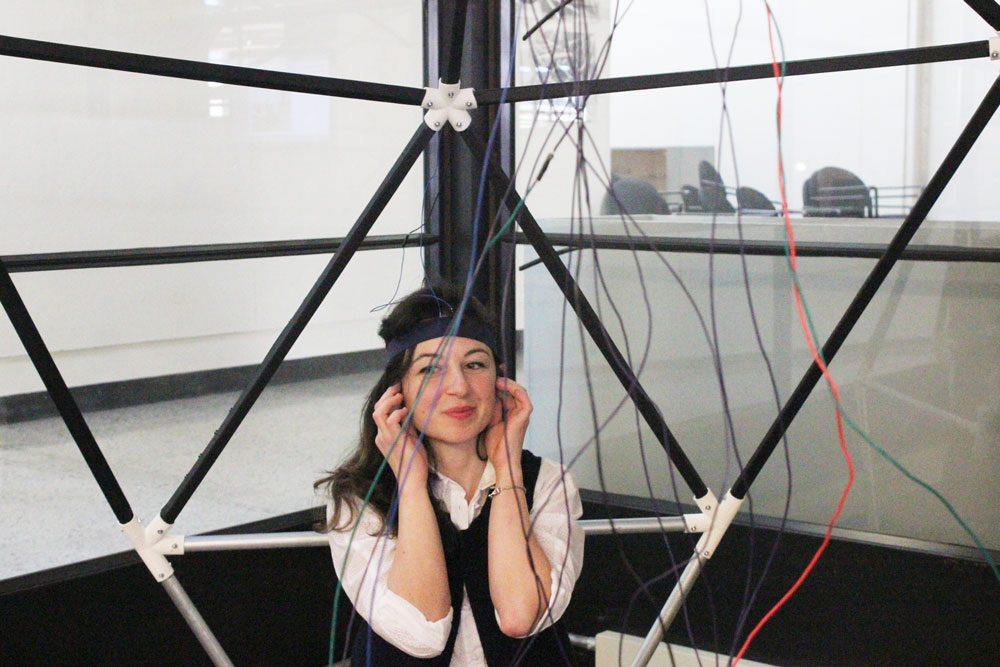
When all the struts were articulated, it was time to stretch the electric cables across them. The aim was to distribute sound (via an amplifier) from the sound source in the middle (for now, it’s a computer; at the end of the Spring semester, it will be a gesture controlled instrument!) to the each bone conduction devide embedded in a forehead band worn by an individual sitting on the metal base.
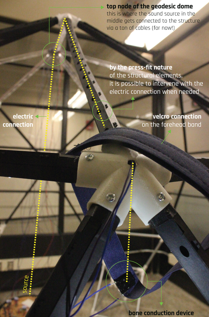
The reason why there are thousand cables is because I need 2 currents (ground abd VCC) for each LED strip embedded polycarbonate strut (there are 3 in total) and 2 currents (ground and VCC) for each bone conduction device (4 in total). Below, how the source is looking like:
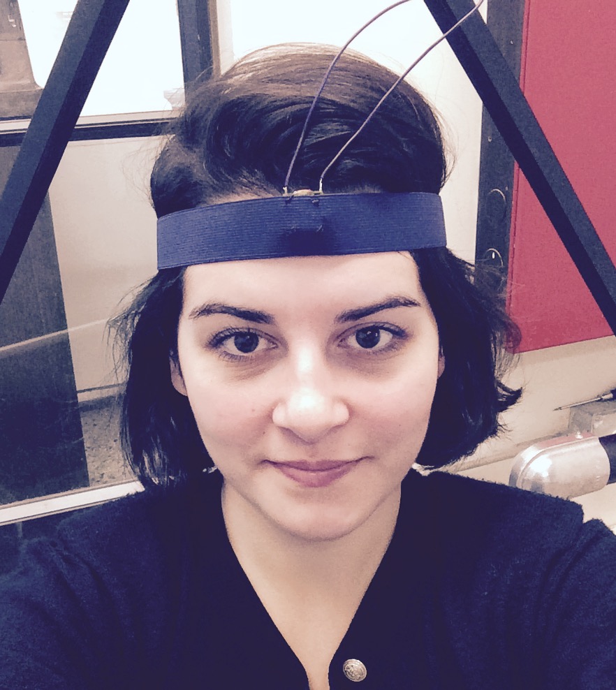
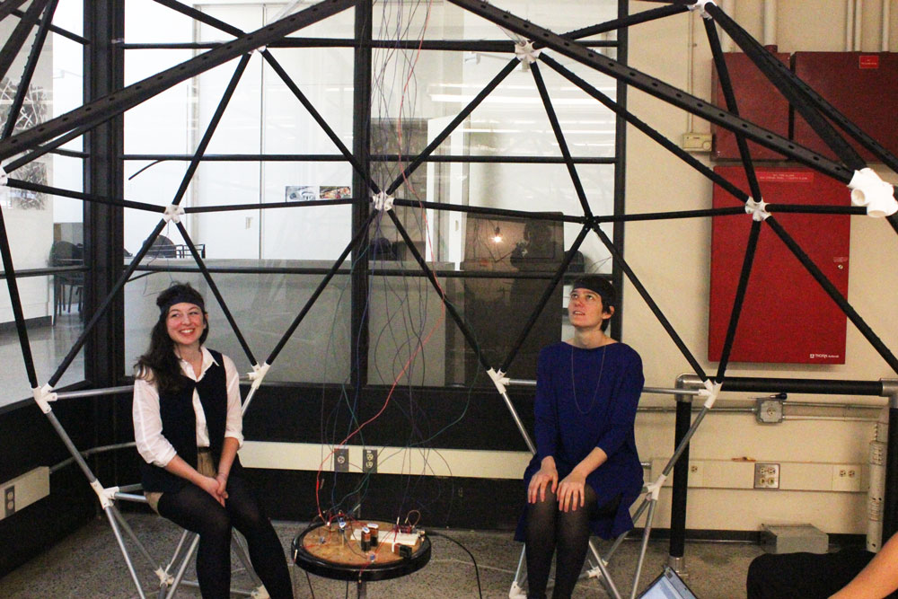
and it was time to demo!

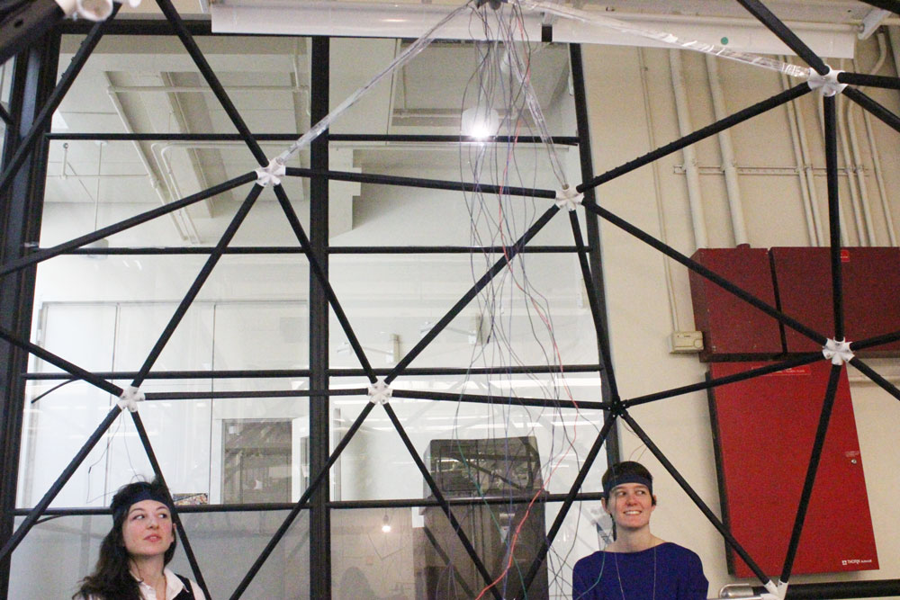
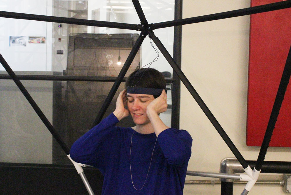
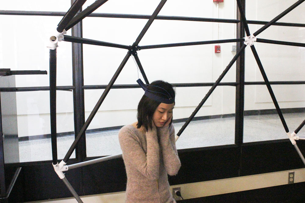
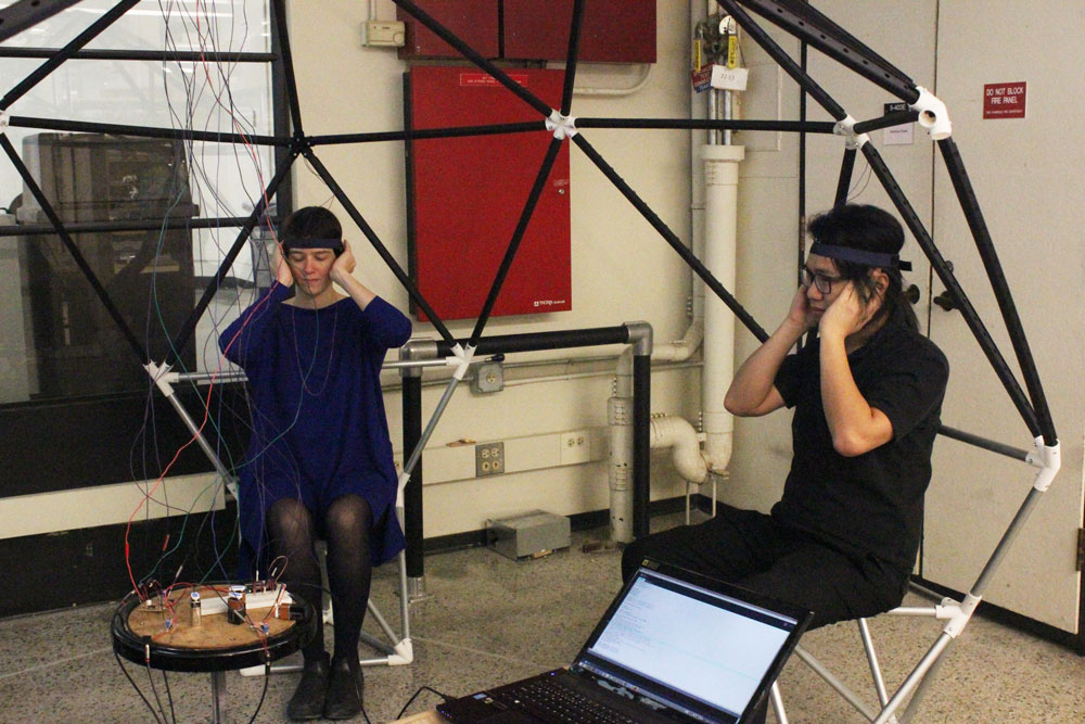
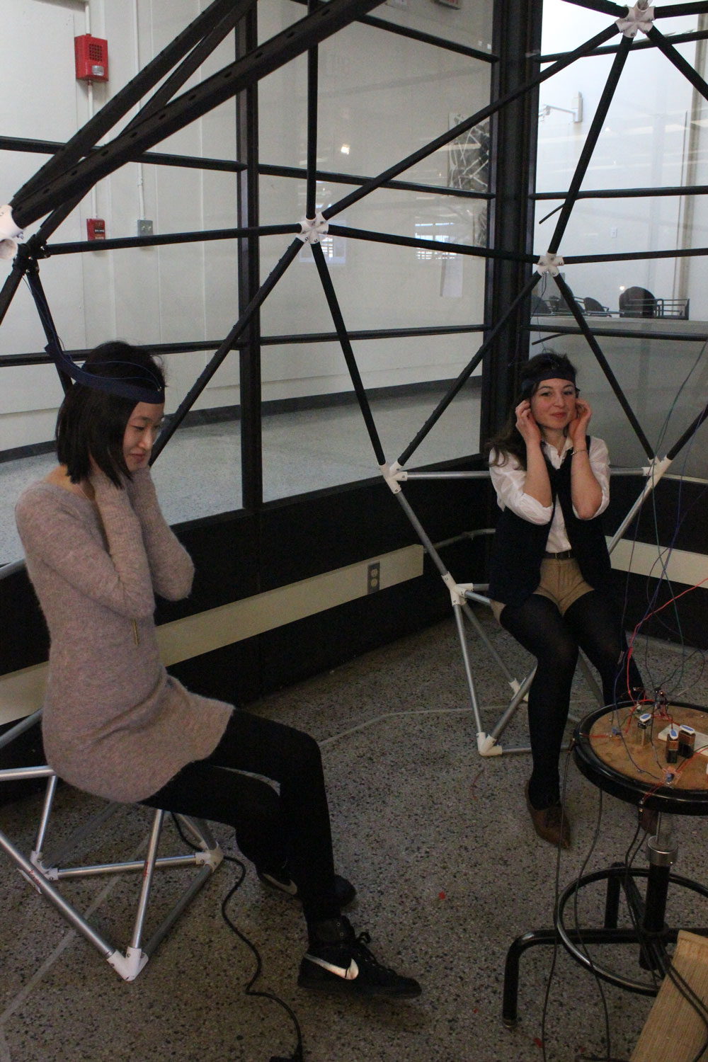
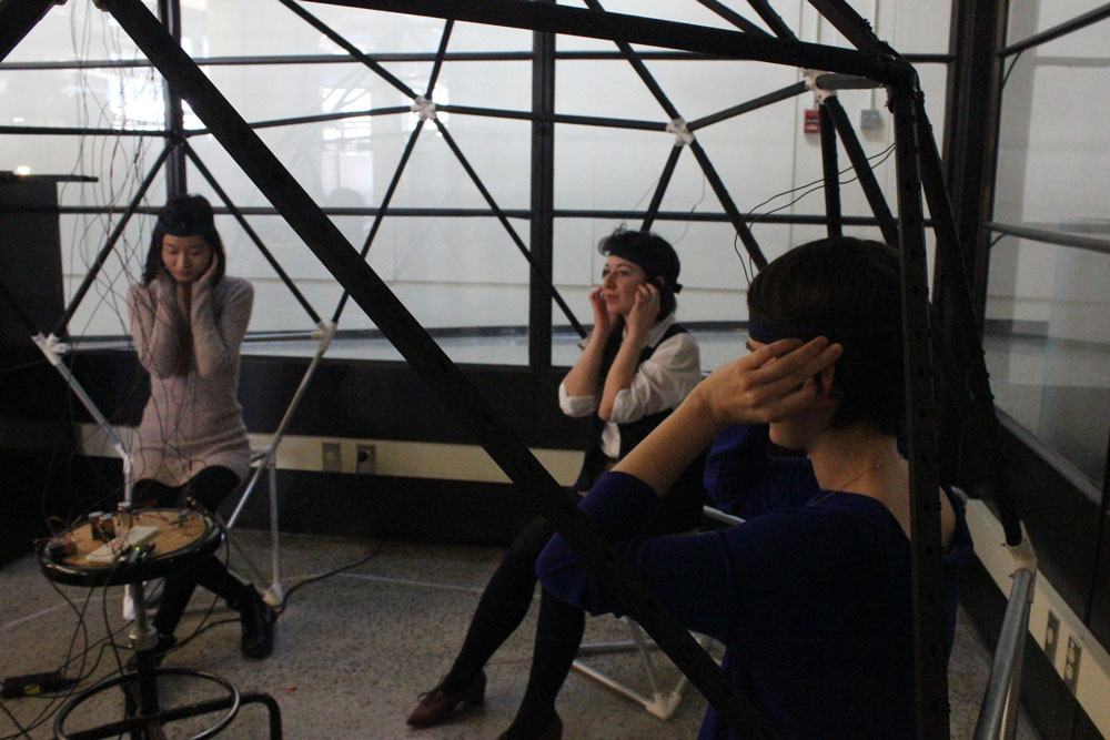
I told the users to plug their ears wittheir fingers to enhance the bone conduction effect!


 Magnetic Field – Hall Effect