Main.Team1 History
Hide minor edits - Show changes to markup
http://newtextiles.media.mit.edu/uploads/Main/Team1_diagram2.png
http://newtextiles.media.mit.edu/2010/uploads/Main/Team1_diagram2.png
http://newtextiles.media.mit.edu/uploads/Main/plan-A.jpg
http://newtextiles.media.mit.edu/2010/uploads/Main/plan-A.jpg
http://newtextiles.media.mit.edu/uploads/Main/plan-B.jpg
http://newtextiles.media.mit.edu/2010/uploads/Main/plan-B.jpg
Because of these setbacks, we decided to create a very simple PCB by hand-cutting strips of Zelt to electrically extend the microcontroller's pins. Also, instead of pushing the pins through the fabric, we stretched them out and stitched them (using conductive thread) to the Zelt instead of using solder. Going with Plan B, our final PCB design, integrated into a functional messenger bag, is shown below! The code that causes our LEDs to spell out "Eat me" is shown on the right of the images of the bag.
Because of these setbacks, we decided to create a very simple PCB by stretching out the microcontroller pins and sewing (instead of soldering) them into the "board." Going with Plan B, our final PCB design, integrated into a functional messenger bag, is shown below! The code that causes our LEDs to spell out "Eat me" is shown on the right of the images of the bag.
Results & video
We are very pleased with how beautiful and robust (both electrically and as functional accessory) our project is! In this first video, our messenger bag is shown in dim lighting so that the flashing LEDs can seen. The five lights (again, only four can be seen because the fifth one is on the back of the bag), flash in order to spell out "Eat me" using Morse code. This second video shows the bag completely in the dark so that only the lights can be seen.
Some of the light coming from the LEDs is a little subtle, possibly due to a weakened LED or non-ideal electrical connection.
Results & experience
We are very pleased with how beautiful and robust (both electrically and as functional accessory) our project is! In this first video, our messenger bag is shown in dim lighting so that the flashing LEDs can seen. The five lights (again, only four can be seen because the fifth one is on the back of the bag), flash in order to spell out "Eat me" using Morse code. This second video shows the bag completely in the dark so that only the lights can be seen. Some of the light coming from the LEDs is a little subtle, possibly due to a weakened LED or non-ideal electrical connection.
In addition to the aforementioned technical issues that resulted in multiple design iterations, our experience with this project made us realize that things almost always don't work as well as they do on paper! We learned to be patient and persistent in testing our microcontroller, especially because none of us are particularly strong in electronics or programming. Regardless, we really appreciated this opportunity to improve our skills and to work on unfamiliar aspects of the project!
We are very pleased with how beautiful and robust (both electrically and as functional accessory) our project is! In this first video, our messenger bag is shown in dim lighting so that the flashing LEDs can seen. The five lights (again, only four can be seen because the fifth one is on the back of the bag), flash in order to spell out "Eat me" using Morse code. This second video2 shows the bag completely in the dark so that only the lights can be seen.
We are very pleased with how beautiful and robust (both electrically and as functional accessory) our project is! In this first video, our messenger bag is shown in dim lighting so that the flashing LEDs can seen. The five lights (again, only four can be seen because the fifth one is on the back of the bag), flash in order to spell out "Eat me" using Morse code. This second video shows the bag completely in the dark so that only the lights can be seen.
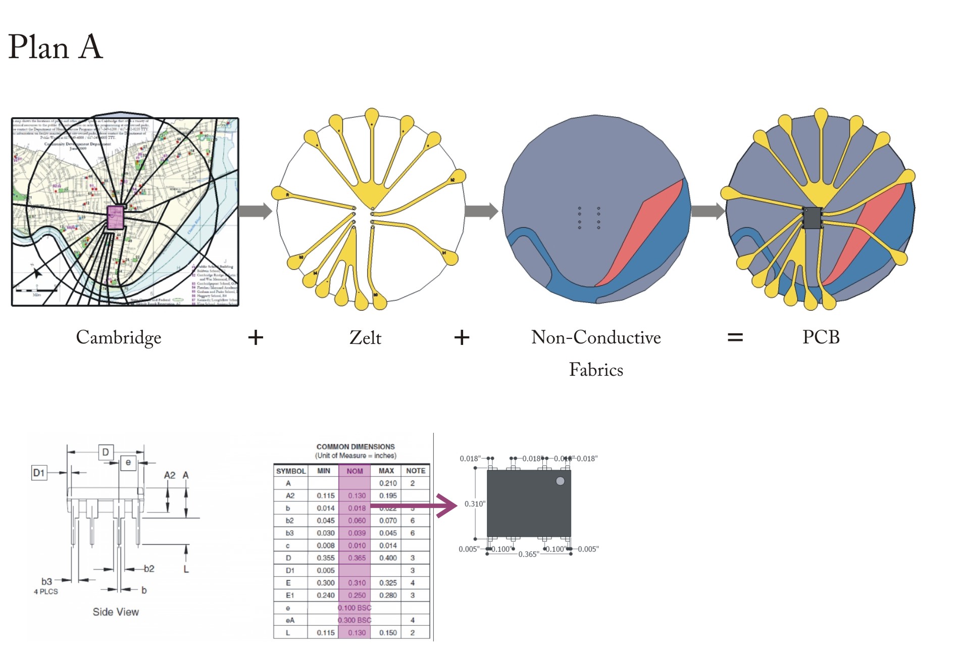
1. We had several issues with the PCB. In terms of the microcontroller sizing, there are three sets of dimensions listed by the manufacturer (Minimum, Normal and Maximum). When we initially designed the PCB layout (shown below under "Plan A"), we used the "Normal" dimensions. After laser-cutting the initial PCB layout, we realized that the pin locations did not match those of our microcontroller. Note: Under "Plan A", a map of Cambridge, MA is shown under the PCB layout; one of our initial concepts for the project was to make an interactive map.
1. We had several issues with the PCB. In terms of the microcontroller sizing, there are three sets of dimensions listed by the manufacturer (Minimum, Normal and Maximum). When we initially designed the PCB layout (shown below under "Plan A"), we used the "Normal" dimensions. After laser-cutting the initial PCB layout, we realized that the pin locations did not match those of our microcontroller, so we might have used the incorrect dimensions. Note: Under "Plan A", a map of Cambridge, MA is shown under the PCB layout; one of our initial concepts for the project was to make an interactive map.
Because of these setbacks, we decided to create a very simple PCB by simply hand-cutting strips of Zelt to electrically extend the microcontroller's pins. Also, instead of pushing the pins through the fabric, we stretched them out and stitched them (using conductive thread) to the Zelt instead of using solder. Going with Plan B, our final PCB design, integrated into a functional messenger bag, is shown below! The code that causes our LEDs to spell out "Eat me" is shown on the right of the images of the bag.
Because of these setbacks, we decided to create a very simple PCB by hand-cutting strips of Zelt to electrically extend the microcontroller's pins. Also, instead of pushing the pins through the fabric, we stretched them out and stitched them (using conductive thread) to the Zelt instead of using solder. Going with Plan B, our final PCB design, integrated into a functional messenger bag, is shown below! The code that causes our LEDs to spell out "Eat me" is shown on the right of the images of the bag.
Why "Eat me"? We initially wanted to program five LED lights to flash the message "Hello world" (in addition to other messages, such as "New textiles" and our names) using Morse code. However, using a microcontroller with only 1 kB of in-system programmable flash, we were limited to short messages with minimal Morse code digits! (For example, "E" and "T" are only one digit each, while "H" and "L" have four digits each.)
Why "Eat me"? We initially wanted to program five LED lights to flash the message "Hello world" (in addition to other messages, such as "New textiles" and our names) using Morse code. However, using a microcontroller with only 1 kB of in-system programmable flash, we were limited to short messages with minimal Morse code digits! (For example, "E" and "T" are only one digit each, while "H" and "L" have four digits each.)
We have constructed a messenger bag that has decorative lights that flash when a metal snap on the side of the bag is closed. For the aesthetics, the bag has five pairs of flowers and bees. Each flower has an LED light in the center of it, and each bee is a resistor; each LED (flower) is connected to its respective resistor (bee) via conductive thread. Each of the flowers flashes its own letter to spell out "Eat me" for the bees! Note: In the image of the bag shown below, only four flowers can be seen, as one is on the back of the bag.
We have constructed a messenger bag that has decorative lights that flash when a metal snap on the side of the bag is closed. For the aesthetics, the bag has five pairs of flowers and bees. Each flower has an LED light in the center of it, and each bee is a resistor; each LED (flower) is connected to its respective resistor (bee) via conductive thread. Each of the flowers flashes its own letter to spell out "Eat me" for the bees! Note: In the image of the bag shown below, only four flowers can be seen, as one is on the back of the bag.
http://newtextiles.media.mit.edu/uploads/Main/Team1_diagram2.png
http://newtextiles.media.mit.edu/uploads/Main/Team1_diagram.png
We are very pleased with how beautiful and robust (both electrically and as functional accessory) our project is! Some of the light coming from the LEDs is a little subtle, possibly due to a weakened LED or non-ideal electrical connection.
In this first video, our messenger bag is shown in dim lighting so that the flashing LEDs can
video2
images
We are very pleased with how beautiful and robust (both electrically and as functional accessory) our project is! In this first video, our messenger bag is shown in dim lighting so that the flashing LEDs can seen. The five lights (again, only four can be seen because the fifth one is on the back of the bag), flash in order to spell out "Eat me" using Morse code. This second video2 shows the bag completely in the dark so that only the lights can be seen.
Some of the light coming from the LEDs is a little subtle, possibly due to a weakened LED or non-ideal electrical connection.
Here are additional images of our project!
video
We are very pleased with how beautiful and robust (both electrically and as functional accessory) our project is! Some of the light coming from the LEDs is a little subtle, possibly due to a weakened LED or non-ideal electrical connection. In this first video, our messenger bag is shown in dim lighting so that the flashing LEDs can
Results & experience
(Show images of bag, video)
Results & video
Because of these setbacks, we decided to create a very simple PCB by simply hand-cutting strips of Zelt to electrically extend the microcontroller's pins. Also, instead of pushing the pins through the fabric, we stretched them out and stitched them (using conductive thread) to the Zelt instead of using solder. Going with Plan B, our final PCB design, integrated into a functional messenger bag, is shown below!
Because of these setbacks, we decided to create a very simple PCB by simply hand-cutting strips of Zelt to electrically extend the microcontroller's pins. Also, instead of pushing the pins through the fabric, we stretched them out and stitched them (using conductive thread) to the Zelt instead of using solder. Going with Plan B, our final PCB design, integrated into a functional messenger bag, is shown below! The code that causes our LEDs to spell out "Eat me" is shown on the right of the images of the bag.
Because of these setbacks, we decided to create a very simple PCB by simply hand-cutting strips of Zelt to electrically extend the microcontroller's pins. Also, instead of pushing the pins through the fabric, we stretched them out and stitched them (using conductive thread) to the Zelt instead of using solder.
Because of these setbacks, we decided to create a very simple PCB by simply hand-cutting strips of Zelt to electrically extend the microcontroller's pins. Also, instead of pushing the pins through the fabric, we stretched them out and stitched them (using conductive thread) to the Zelt instead of using solder. Going with Plan B, our final PCB design, integrated into a functional messenger bag, is shown below!
So for the second plan, we made a shoulder bag, with a little 'button switch' on the side so that a wearer can use it as a normal bag, and if she feels like it, she can turn on the switch and her bag will be outputting a subtle message of 'eat me'. The LED works, but the effect is really subtle, since the LEDs are not very bright.
Because of these setbacks, we decided to create a very simple PCB by simply hand-cutting strips of Zelt to electrically extend the microcontroller's pins. Also, instead of pushing the pins through the fabric, we stretched them out and stitched them (using conductive thread) to the Zelt instead of using solder.
Concepts iteration & Design Process
Concept iteration & Design Process
2. Also for the initial PCB layout (shown in "Plan A"), when we laser-cut the materials we put the Zelt fabric upside-down, but we did not mirror the images. Therefore,
2. Also for the initial PCB layout (shown in "Plan A"), when we laser-cut the materials we put the Zelt fabric upside-down without flipping the image we were cutting. Normally this would not be too much of an issue, but we planned to have the Zelt be part of the aesthetics of our project, so it had to be right-side up.
2. Second Issue was the printing process. We putted the Zelt fabrics upside down on the laser cutter but didn’t mirror the images, so it was printed in the wrong way. Another issue was the narrow gap near the microcontroller pins.
2. Also for the initial PCB layout (shown in "Plan A"), when we laser-cut the materials we put the Zelt fabric upside-down, but we did not mirror the images. Therefore,
1. We had several issues with the PCB. In terms of the microcontroller sizing, there are three sets of dimensions listed by the manufacturer (Minimum, Normal and Maximum). When we initially designed the PCB layout (shown below under "Plan A"), we used the "Normal" dimensions. After laser-cutting the initial PCB layout, we realized that the pin locations did not match those of our microcontroller. So the chip’s pins need to be stretched out to reach the holes on the fabrics. Second Issue was the printing process. We putted the Zelt fabrics upside down on the laser cutter but didn’t mirror the images, so it was printed in the wrong way. Another issue was the narrow gap near the microcontroller pins.
1. We had several issues with the PCB. In terms of the microcontroller sizing, there are three sets of dimensions listed by the manufacturer (Minimum, Normal and Maximum). When we initially designed the PCB layout (shown below under "Plan A"), we used the "Normal" dimensions. After laser-cutting the initial PCB layout, we realized that the pin locations did not match those of our microcontroller. Note: Under "Plan A", a map of Cambridge, MA is shown under the PCB layout; one of our initial concepts for the project was to make an interactive map.
2. Second Issue was the printing process. We putted the Zelt fabrics upside down on the laser cutter but didn’t mirror the images, so it was printed in the wrong way. Another issue was the narrow gap near the microcontroller pins.
1. We had several issues with the PCB. In terms of the microcontroller sizing, there are three sets of dimensions listed by the manufacturer (Minimum, Normal and Maximum). When we initially designed the PCB layout (shown below under "Plan A"), we used the "Normal" dimensions. Apparently, it was not fit perfectly. So the chip’s pins need to be stretched out to reach the holes on the fabrics. Second Issue was the printing process. We putted the Zelt fabrics upside down on the laser cutter but didn’t mirror the images, so it was printed in the wrong way. Another issue was the narrow gap near the microcontroller pins.
1. We had several issues with the PCB. In terms of the microcontroller sizing, there are three sets of dimensions listed by the manufacturer (Minimum, Normal and Maximum). When we initially designed the PCB layout (shown below under "Plan A"), we used the "Normal" dimensions. After laser-cutting the initial PCB layout, we realized that the pin locations did not match those of our microcontroller. So the chip’s pins need to be stretched out to reach the holes on the fabrics. Second Issue was the printing process. We putted the Zelt fabrics upside down on the laser cutter but didn’t mirror the images, so it was printed in the wrong way. Another issue was the narrow gap near the microcontroller pins.
We also have several issues for the PCB. First is the microcontroller size. There are three dimension versions from the guidelines (Minimum, Normal and Maximum) and we tried the Normal one. Apparently, it was not fit perfectly. So the chip’s pins need to be stretched out to reach the holes on the fabrics. Second Issue was the printing process. We putted the Zelt fabrics upside down on the laser cutter but didn’t mirror the images, so it was printed in the wrong way. Another issue was the narrow gap near the microcontroller pins.
1. We had several issues with the PCB. In terms of the microcontroller sizing, there are three sets of dimensions listed by the manufacturer (Minimum, Normal and Maximum). When we initially designed the PCB layout (shown below under "Plan A"), we used the "Normal" dimensions. Apparently, it was not fit perfectly. So the chip’s pins need to be stretched out to reach the holes on the fabrics. Second Issue was the printing process. We putted the Zelt fabrics upside down on the laser cutter but didn’t mirror the images, so it was printed in the wrong way. Another issue was the narrow gap near the microcontroller pins.
We have constructed a messenger bag that has decorative lights that flash when a metal snap on the side of the bag is closed. For the aesthetics, the bag has five pairs of flowers and bees. Each flower has an LED light in the center of it, and each bee is a resistor; each LED (flower) is connected to its respective resistor (bee) via conductive thread. Each of the flowers flashes its own letter to spell out "Eat me" for the bees! Note: In the image of the bag shown below, only five flowers can be seen, as one is on the back of the bag.
We have constructed a messenger bag that has decorative lights that flash when a metal snap on the side of the bag is closed. For the aesthetics, the bag has five pairs of flowers and bees. Each flower has an LED light in the center of it, and each bee is a resistor; each LED (flower) is connected to its respective resistor (bee) via conductive thread. Each of the flowers flashes its own letter to spell out "Eat me" for the bees! Note: In the image of the bag shown below, only four flowers can be seen, as one is on the back of the bag.
Why "Eat me"? We initially wanted to program five LED lights to flash the message "Hello world" (in addition to other messages, such as "New textiles" and our names) using Morse code. However, using a microcontroller with only 1 kB of in-system programmable flash, we were limited to short messages with minimal Morse code digits! (For example, "E" and "T" are only one digit each, while "H" and "L" have four digits each.)
Why "Eat me"? We initially wanted to program five LED lights to flash the message "Hello world" (in addition to other messages, such as "New textiles" and our names) using Morse code. However, using a microcontroller with only 1 kB of in-system programmable flash, we were limited to short messages with minimal Morse code digits! (For example, "E" and "T" are only one digit each, while "H" and "L" have four digits each.)
Primary (electrical) system components
Primary (electrical) system components
System overview
System overview
Concepts iteration & Design Process
Concepts iteration & Design Process
Results & experience
Results & experience
We had several significant design iterations due to various issues that came up during the construction process:
To arrive at the final design described above, we had several significant design iterations due to various issues that came up during the construction process:
Concepts & Design Process
Concepts iteration & Design Process
We had several significant design iterations due to various issues that came up during the construction process:
Input: A switch that either completes or opens the circuit. The switch is a metal snap, whose two halves are electrically connected--via conductive wire--to two open ends of the circuit that connect the battery, the microcontroller, and each LED-resistor pair.\\
Input: A switch that either completes or opens the circuit. Here, the switch is a metal snap, whose two halves are electrically connected--via conductive thread--to two open ends of the circuit that connect the battery, the microcontroller, and each LED-resistor pair.\\
We have constructed a messenger bag that has decorative lights that flash when a metal snap on the side of the bag is closed. For the aesthetics, the bag has five pairs of flowers and bees. Each flower has an LED light in the center of it, and each bee is a resistor; each LED (flower) is connected to its respective resistor (bee) via conductive thread. Each of the flowers flashes its own letter to spell out "Eat me" for the bees! Note: In the image of the bag shown below, only five flowers can be seen, as one is on the back of the bag.
We have constructed a messenger bag that has decorative lights that flash when a metal snap on the side of the bag is closed. For the aesthetics, the bag has five pairs of flowers and bees. Each flower has an LED light in the center of it, and each bee is a resistor; each LED (flower) is connected to its respective resistor (bee) via conductive thread. Each of the flowers flashes its own letter to spell out "Eat me" for the bees! Note: In the image of the bag shown below, only five flowers can be seen, as one is on the back of the bag.
We have constructed a messenger bag that has decorative lights that flash when a metal snap on the side of the bag is closed. For the aesthetics, the bag has five pairs of flowers and bees. Each flower has an LED light in the center of it, and each bee is a resistor; each LED (flower) is connected to its respective resistor (bee) via conductive thread. Each of the flowers flashes its own letter to spell out "Eat me" for the bees! Note: In the image of the bag shown below, only five flowers can be seen, as one is on the back of the bag.
We have constructed a messenger bag that has decorative lights that flash when a metal snap on the side of the bag is closed. For the aesthetics, the bag has five pairs of flowers and bees. Each flower has an LED light in the center of it, and each bee is a resistor; each LED (flower) is connected to its respective resistor (bee) via conductive thread. Each of the flowers flashes its own letter to spell out "Eat me" for the bees! Note: In the image of the bag shown below, only five flowers can be seen, as one is on the back of the bag.
We have constructed a messenger bag that has decorative lights that flash when a metal snap on the side of the bag is closed. For the aesthetics, the bag has five pairs of flowers and bees. Each flower has an LED light in the center of it, and each bee is a resistor; each LED (flower) is connected to its respective resistor (bee) via conductive thread. Each of the flowers flashes its own letter to spell out "Eat me" for the bees!
We have constructed a messenger bag that has decorative lights that flash when a metal snap on the side of the bag is closed. For the aesthetics, the bag has five pairs of flowers and bees. Each flower has an LED light in the center of it, and each bee is a resistor; each LED (flower) is connected to its respective resistor (bee) via conductive thread. Each of the flowers flashes its own letter to spell out "Eat me" for the bees! Note: In the image of the bag shown below, only five flowers can be seen, as one is on the back of the bag.
Circuit-wise, our system has five outputs and one input:
Circuit-wise, our system has five outputs and one input:\\
Circuit-wise, our system has five outputs and one input:
Outputs: 5 LED lights (one for each of the microncontroller's independent outputs).
Input: A switch that either completes or opens the circuit. The switch is a metal snap, whose two halves are electrically connected--via conductive wire--to two open ends of the circuit that connect the battery, the microcontroller, and each LED-resistor pair.
Circuit-wise, our system has five outputs and one input.
Outputs: 5 LED lights (one for each of the microncontroller's independent outputs).
Input: A switch that either completes or opens the circuit. The switch connection is between the negative terminal of the microcontroller (which is effectively extended via conductive thread) and the negative pins of each of the LEDs (also effectively extended via conductive thread). In our system, the microcontroller is attached to the flap of the messenger bag that opens and closes, while the LEDs are sewn into the main body of the bag. When the bag is closed, a physical (and therefore electrical) connection is made between the microcontroller and the LEDs, thus completing the circuit.
(Show picture of bag with main components labeled: LEDs, microcontroller, conductive thread)
(Show close-up picture of PCB and label components; emphasize that pins are sewn to connections instead of soldered)
We have constructed a messenger bag that has decorative lights that flash when a metal snap on the side of the bag is closed. For the aesthetics, the bag has five pairs of flowers and bees. Each flower has an LED light in the center of it, and each bee is a resistor; each LED (flower) is connected to its respective resistor (bee) via conductive thread! Each of the flowers flashes its own letter to spell out "Eat me" for the bees!
We have constructed a messenger bag that has decorative lights that flash when a metal snap on the side of the bag is closed. For the aesthetics, the bag has five pairs of flowers and bees. Each flower has an LED light in the center of it, and each bee is a resistor; each LED (flower) is connected to its respective resistor (bee) via conductive thread. Each of the flowers flashes its own letter to spell out "Eat me" for the bees!
We have constructed a messenger bag that has decorative lights that flash when a metal snap on the side of the bag is closed. For the aesthetics, the bag has five pairs of flowers and bees. Each flower has an LED light in the center of it, and each bee is a resistor; each LED (flower) is connected to its respective resistor (bee) via conductive thread. Each of the flowers flashes its own letter to spell out "Eat me" for the bees!
We have constructed a messenger bag that has decorative lights that flash when a metal snap on the side of the bag is closed.
We have constructed a messenger bag that has decorative lights that flash when a metal snap on the side of the bag is closed. For the aesthetics, the bag has five pairs of flowers and bees. Each flower has an LED light in the center of it, and each bee is a resistor; each LED (flower) is connected to its respective resistor (bee) via conductive thread. Each of the flowers flashes its own letter to spell out "Eat me" for the bees!
We have constructed a messenger bag that has decorative lights that flash when the bag is closed. Circuit-wise, our system has five outputs and one input.
We have constructed a messenger bag that has decorative lights that flash when a metal snap on the side of the bag is closed.
http://newtextiles.media.mit.edu/uploads/Main/Team1_diagram.png
Circuit-wise, our system has five outputs and one input.
http://newtextiles.media.mit.edu/uploads/Main/Team1_diagram.png
Primary (electrical) system components
Primary (electrical) system components
System overview
System overview
Concepts & Design Process
Concepts & Design Process
Results & experience
Results & experience
Primary (electrical) system components
Primary (electrical) system components
System overview
System overview
Concepts & Design Process
Concepts & Design Process
Results & experience
Results & experience
http://newtextiles.media.mit.edu/uploads/Main/Team1_diagram.png
Why "Eat me"? We initially wanted to program five LED lights to flash the message "Hello world" (in addition to other messages, such as "New textiles" and our names) using Morse code. However, using a microcontroller with only 1 kB of in-system programmable flash, we were limited to short messages with minimal Morse code digits! (For example, "E" and "T" are only one digit each, while "H" and "L" have four digits each.)
Why "Eat me"? We initially wanted to program five LED lights to flash the message "Hello world" (in addition to other messages, such as "New textiles" and our names) using Morse code. However, using a microcontroller with only 1 kB of in-system programmable flash, we were limited to short messages with minimal Morse code digits! (For example, "E" and "T" are only one digit each, while "H" and "L" have four digits each.)
+A battery
+A battery\\
Outputs: 5 LED lights (one for each of the microncontroller's independent outputs).
Input: A switch that either completes or opens the circuit. The switch connection is between the negative terminal of the microcontroller (which is effectively extended via conductive thread) and the negative pins of each of the LEDs (also effectively extended via conductive thread). In our system, the microcontroller is attached to the flap of the messenger bag that opens and closes, while the LEDs are sewn into the main body of the bag. When the bag is closed, a physical (and therefore electrical) connection is made between the microcontroller and the LEDs, thus completing the circuit.\\
+One resistor per LED
+A battery
(:markup:)
(:markupend:)
(:markup:)
(:markupend:)
By Angela, Nadia, Rizal, and Yang
By Angela, Nadia, Rizal, and Yang
Why "Eat me"? We initially wanted to program five LED lights to flash the message "Hello world" (in addition to other messages, such as "New textiles" and our names) using Morse code. However, using a microcontroller with only 1 kB of in-system programmable flash, we were limited to short messages with minimal Morse code digits! (For example, "E" and "T" are only one digit each, while "H" and "L" have four digits each.)
Primary (electrical) system components
System overview
System overview
Outputs: 5 LED lights (one for each of the microncontroller's independent outputs).
Input: A switch that either completes or opens the circuit. The switch connection is between the negative terminal of the microcontroller (which is effectively extended via conductive thread) and the negative pins of each of the LEDs (also effectively extended via conductive thread). In our system, the microcontroller is attached to the flap of the messenger bag that opens and closes, while the LEDs are sewn into the main body of the bag. When the bag is closed, a physical (and therefore electrical) connection is made between the microcontroller and the LEDs, thus completing the circuit.
Concepts & Design Process
Concepts & Design Process
Results & experience
Results & experience
By Angela, Nadia, Rizal, and Yang
By Angela, Nadia, Rizal, and Yang
Why "Eat me"? We initially wanted to program five LED lights to flash the message "Hello world" (in addition to other messages, such as "New textiles" and our names) using Morse code. However, using a microcontroller with only 1 kB of in-system programmable flash, we were limited to short messages with minimal Morse code digits! (For example, "E" and "T" are only one digit each, while "H" and "L" have four digits each.)
Why "Eat me"? We initially wanted to program five LED lights to flash the message "Hello world" (in addition to other messages, such as "New textiles" and our names) using Morse code. However, using a microcontroller with only 1 kB of in-system programmable flash, we were limited to short messages with minimal Morse code digits! (For example, "E" and "T" are only one digit each, while "H" and "L" have four digits each.)
Outputs: 5 LED lights (one for each of the microncontroller's independent outputs).
Input: A switch that either completes or opens the circuit. The switch connection is between the negative terminal of the microcontroller (which is effectively extended via conductive thread) and the negative pins of each of the LEDs (also effectively extended via conductive thread). In our system, the microcontroller is attached to the flap of the messenger bag that opens and closes, while the LEDs are sewn into the main body of the bag. When the bag is closed, a physical (and therefore electrical) connection is made between the microcontroller and the LEDs, thus completing the circuit.\\
\\
---
\\
---
\\
---
---
video video2 images
By Angela, Nadia, Rizal, and Yang
By Angela, Nadia, Rizal, and Yang
By Angela, Nadia, Rizal, and Yang
By Angela, Nadia, Rizal, and Yang
Why "Eat me"? We initially wanted to program five LED lights to flash the message "Hello world" (in addition to other messages, such as "New textiles" and our names) using Morse code. However, using a microcontroller with only 1 kB of in-system programmable flash, we were limited to short messages with minimal Morse code digits! (For example, "E" and "T" are only one digit each, while "H" and "L" have four digits each.)
Why "Eat me"? We initially wanted to program five LED lights to flash the message "Hello world" (in addition to other messages, such as "New textiles" and our names) using Morse code. However, using a microcontroller with only 1 kB of in-system programmable flash, we were limited to short messages with minimal Morse code digits! (For example, "E" and "T" are only one digit each, while "H" and "L" have four digits each.)
Why "Eat me"? We initially wanted to program five LED lights to flash the message "Hello world" (in addition to other messages, such as "New textiles" and our names) using Morse code. However, using a microcontroller with only 1 kB of in-system programmable flash, we were limited to short messages with minimal Morse code digits! (For example, "E" and "T" are only one digit each, while "H" and "L" have four digits each.)
Why "Eat me"? We initially wanted to program five LED lights to flash the message "Hello world" (in addition to other messages, such as "New textiles" and our names) using Morse code. However, using a microcontroller with only 1 kB of in-system programmable flash, we were limited to short messages with minimal Morse code digits! (For example, "E" and "T" are only one digit each, while "H" and "L" have four digits each.)
\\
\\!!Primary (electrical) system components
!!Primary (electrical) system components
Primary (electrical) system components
\\!!Primary (electrical) system components
(Describe input, outputs)\\
Initial concepts & Design Process
Concepts & Design Process
Primary system components
Primary (electrical) system components
Our system has five outputs and one input.
We have constructed a messenger bag that has decorative lights that flash when the bag is closed. Circuit-wise, our system has five outputs and one input.
Input: A switch that either completes or opens the circuit. The switch connection is between the negative terminal of the microcontroller (which is effectively extended via conductive thread) and the negative pins of each of the LEDs (also effectively extended via conductive thread). In our system, the microcontroller is attached to the flap of the messenger bag that opens and closes, while the LEDs and their sewn into the main body of the bag. When the bag is closed, a physical (and therefore electrical) connection is made between the microcontroller and the LEDs, thus completing the circuit.\\
Input: A switch that either completes or opens the circuit. The switch connection is between the negative terminal of the microcontroller (which is effectively extended via conductive thread) and the negative pins of each of the LEDs (also effectively extended via conductive thread). In our system, the microcontroller is attached to the flap of the messenger bag that opens and closes, while the LEDs are sewn into the main body of the bag. When the bag is closed, a physical (and therefore electrical) connection is made between the microcontroller and the LEDs, thus completing the circuit.\\
Why "Eat me"? We initially wanted to program five LED lights to flash the message "Hello world" (in addition to other messages, such as "New textiles" and our names) using Morse code. However, using a microcontroller with only 1 kB of in-system programmable flash, we were limited to short messages with minimal Morse code digits! (For example, "E" and "T" are only one digit each, while "H" and "L" have four digits each.)
Why "Eat me"? We initially wanted to program five LED lights to flash the message "Hello world" (in addition to other messages, such as "New textiles" and our names) using Morse code. However, using a microcontroller with only 1 kB of in-system programmable flash, we were limited to short messages with minimal Morse code digits! (For example, "E" and "T" are only one digit each, while "H" and "L" have four digits each.)
Why "Eat me"? We initially wanted to program five LED lights to flash the message "Hello world" (in addition to other messages, such as "New textiles" and our names) using Morse code. However, using a microcontroller with only 1 kB of in-system programmable flash, we were limited to short messages with minimal Morse code digits! (For example, "E" and "T" are only one digit each, while "H" and "L" have four digits each.)
Why "Eat me"? We initially wanted to program five LED lights to flash the message "Hello world" (in addition to other messages, such as "New textiles" and our names) using Morse code. However, using a microcontroller with only 1 kB of in-system programmable flash, we were limited to short messages with minimal Morse code digits! (For example, "E" and "T" are only one digit each, while "H" and "L" have four digits each.)
Design Process
Initial concepts & Design Process
Input: A switch that either completes or opens the circuit. The switch connection is between the negative terminal of the microcontroller (which is effectively extended via conductive thread) and the negative pins of each of the LEDs (also effectively extended via conductive thread.) In our system, the microcontroller is attached to the flap of the messenger bag that opens and closes, while the LEDs and their sewn into the main body of the bag. When the bag is closed, a physical (and therefore electrical) connection is made between the microcontroller and the LEDs, thus completing the circuit.\\
Input: A switch that either completes or opens the circuit. The switch connection is between the negative terminal of the microcontroller (which is effectively extended via conductive thread) and the negative pins of each of the LEDs (also effectively extended via conductive thread). In our system, the microcontroller is attached to the flap of the messenger bag that opens and closes, while the LEDs and their sewn into the main body of the bag. When the bag is closed, a physical (and therefore electrical) connection is made between the microcontroller and the LEDs, thus completing the circuit.\\
Our system has one input and five outputs.
Our system has five outputs and one input.
Our system has one input and five outputs.\\
Our system has one input and five outputs.
(Describe input, outputs) (Show picture of bag with main components labeled: LEDs, microcontroller, conductive thread)
(Describe input, outputs)
(Show picture of bag with main components labeled: LEDs, microcontroller, conductive thread)\\
(Describe input, outputs) (Show picture of bag with main components labeled: LEDs, microcontroller, conductive thread) (Show close-up picture of PCB and label components; emphasize that pins are sewn to connections instead of soldered)
Input: A switch that either completes or opens the circuit. The switch connection is between the negative terminal of the microcontroller and the negative pins of each of the LEDs, which are effectively extended via conductive thread.
Input: A switch that either completes or opens the circuit. The switch connection is between the negative terminal of the microcontroller (which is effectively extended via conductive thread) and the negative pins of each of the LEDs (also effectively extended via conductive thread.) In our system, the microcontroller is attached to the flap of the messenger bag that opens and closes, while the LEDs and their sewn into the main body of the bag. When the bag is closed, a physical (and therefore electrical) connection is made between the microcontroller and the LEDs, thus completing the circuit.\\
System overview\\
System overview
System overview
System overview\\
Our system has one input and five outputs. Outputs: 5 LED lights (one for each of the microncontroller's independent outputs)
Our system has one input and five outputs.
Outputs: 5 LED lights (one for each of the microncontroller's independent outputs).\\
Our system has one input and five outputs. Outputs: 5 LED lights (one for each of the microncontroller's independent outputs) Input: A switch that either completes or opens the circuit. The switch connection is between the negative terminal of the microcontroller and the negative pins of each of the LEDs, which are effectively extended via conductive thread.
(Show images of bag, video)
(Show images of bag, video)
So for the second plan, we made a shoulder bag, with a little 'button switch' on the side so that a wearer can use it as a normal bag, and if she feels like it, she can turn on the switch and her bag will be outputting a subtle message of 'eat me'. The LED works, but the effect is really subtle, since the LEDs are not very bright.
(Describe input, outputs) (Show picture of bag with main components labeled: LEDs, microcontroller, conductive thread) (Show close-up picture of PCB and label components; emphasize that pins are sewn to connections instead of soldered)
System overview
Why "Eat me"? We initially wanted to program five LED lights to flash the message "Hello world" (in addition to other messages, such as "New textiles" and our names) using Morse code. However, with a microcontroller with only 1 kB of in-system programmable flash, we were limited to short messages with minimal Morse code digits! (For example, "E" and "T" are only one digit each, while "H" and "L" have four digits each.)
System overview
Why "Eat me"? We initially wanted to program five LED lights to flash the message "Hello world" (in addition to other messages, such as "New textiles" and our names) using Morse code. However, using a microcontroller with only 1 kB of in-system programmable flash, we were limited to short messages with minimal Morse code digits! (For example, "E" and "T" are only one digit each, while "H" and "L" have four digits each.)
Primary system components
We also have several issues for the PCB. First is the microcontroller size. There are three dimension versions from the guidelines (Minimum, Normal and Maximum) and we tried the Normal one. Apparently, it was not fit perfectly. So the chip’s pins need to be stretched out to reach the holes on the fabrics. Second Issue was the printing process. We putted the Zelt fabrics upside down on the laser cutter but didn’t mirror the images, so it was printed in the wrong way. Another issue was the narrow gap between the printed PCB.
We also have several issues for the PCB. First is the microcontroller size. There are three dimension versions from the guidelines (Minimum, Normal and Maximum) and we tried the Normal one. Apparently, it was not fit perfectly. So the chip’s pins need to be stretched out to reach the holes on the fabrics. Second Issue was the printing process. We putted the Zelt fabrics upside down on the laser cutter but didn’t mirror the images, so it was printed in the wrong way. Another issue was the narrow gap near the microcontroller pins.
http://newtextiles.media.mit.edu/uploads/Main/plan-A.jpg
We also have several issues for the PCB. First is the microcontroller size. There are three dimension versions from the guidelines (Minimum, Normal and Maximum) and we tried the Normal one. Apparently, it was not fit perfectly. So the chip’s pins need to be stretched out to reach the holes on the fabrics. Second Issue was the printing process. We putted the Zelt fabrics upside down on the laser cutter but didn’t mirror the images, so it was printed in the wrong way. Another issue was the narrow gap between the printed PCB.
http://newtextiles.media.mit.edu/uploads/Main/plan-A.jpg
http://newtextiles.media.mit.edu/uploads/Main/plan-B.jpg
http://newtextiles.media.mit.edu/uploads/Main/plan-B.jpg
Primary system components
System overview
System overview
Design Process
http://newtextiles.media.mit.edu/uploads/Main/plan-B.jpg
http://newtextiles.media.mit.edu/uploads/Main/plan-A.jpg
http://newtextiles.media.mit.edu/uploads/Main/plan-A.jpg
http://newtextiles.media.mit.edu/uploads/Main/plan-A.jpg
http://newtextiles.media.mit.edu/uploads/Main/plan-A.jpg
http://newtextiles.media.mit.edu/uploads/Main/plan-A.jpg
( )
)
http://newtextiles.media.mit.edu/uploads/Main/plan-A.jpg http://newtextiles.media.mit.edu/uploads/Main/plan-A.jpg
http://newtextiles.media.mit.edu/uploads/Main/plan-A.jpg http://newtextiles.media.mit.edu/uploads/Main/plan-A.jpg
http://newtextiles.media.mit.edu/uploads/Main/plan-A.jpg http://newtextiles.media.mit.edu/uploads/Main/plan-A.jpg
http://newtextiles.media.mit.edu/uploads/Main/plan-A.jpg http://newtextiles.media.mit.edu/uploads/Main/plan-A.jpg
http://newtextiles.media.mit.edu/uploads/Main/glove-b-small.jpg http://newtextiles.media.mit.edu/uploads/Main/glove-b-small.jpg
http://newtextiles.media.mit.edu/uploads/Main/plan-A.jpg http://newtextiles.media.mit.edu/uploads/Main/plan-A.jpg
http://newtextiles.media.mit.edu/uploads/Main/glove-b-small.jpg http://newtextiles.media.mit.edu/uploads/Main/glove-b-small.jpg
http://newtextiles.media.mit.edu/uploads/Main/glove-b-small.jpg http://newtextiles.media.mit.edu/uploads/Main/glove-b-small.jpg
(http://newtextiles.media.mit.edu/uploads/Main/glove-b-small.jpg) (http://newtextiles.media.mit.edu/uploads/Main/glove-b-small.jpg)
http://newtextiles.media.mit.edu/uploads/Main/glove-b-small.jpg http://newtextiles.media.mit.edu/uploads/Main/glove-b-small.jpg
(plan-A.jpg) (plan-A.jpg)
(http://newtextiles.media.mit.edu/uploads/Main/glove-b-small.jpg) (http://newtextiles.media.mit.edu/uploads/Main/glove-b-small.jpg)
(plan-A.jpg) (plan-A.jpg)
()
System overview
(Describe input, outputs) (Show picture of bag with main components labeled: LEDs, microcontroller, conductive thread) (Show close-up picture of PCB and label components; emphasize that pins are sewn to connections instead of soldered)
Results & experience
(Show images of bag, video)
A "Hello World" (or, rather, "Eat Me") fabric PCB\\
A "Hello World" (or, rather, "Eat Me") fabric PCB
A "Hello World" (or, rather, "Eat Me") fabric PCB
\\!!By Angela, Nadia, Rizal, and Yang
A "Hello World" (or, rather, "Eat Me") fabric PCB
By Angela, Nadia, Rizal, and Yang
By Angela, Nadia, Rizal, and Yang
\\!!By Angela, Nadia, Rizal, and Yang
!!By Angela, Nadia, Rizal, and Yang
By Angela, Nadia, Rizal, and Yang
By Angela, Nadia, Rizal, and Yang
!!By Angela, Nadia, Rizal, and Yang
Why "Eat me"? We initially wanted to program five LED lights to flash the message "Hello world" (in addition to other messages, such as "New textiles" and our names) using Morse code. However, with a microcontroller with only 1 kB of in-system programmable flash, we were limited to short messages with minimal Morse code digits!
Why "Eat me"? We initially wanted to program five LED lights to flash the message "Hello world" (in addition to other messages, such as "New textiles" and our names) using Morse code. However, with a microcontroller with only 1 kB of in-system programmable flash, we were limited to short messages with minimal Morse code digits! (For example, "E" and "T" are only one digit each, while "H" and "L" have four digits each.)
Why "Eat me"? We initially wanted to program five LED lights to flash the message "Hello world" (in addition to other messages, such as "New textiles" and our names) using Morse code. However, with a microcontroller with only 1 kB of in-system programmable flash, we were limited to short messages with minimal Morse code digits!
Why "Eat me"? We initially wanted to program five LED lights to flash the message "Hello world" (in addition to other messages, such as "New textiles" and our names) using morse code. However, with a microcontroller with only 1 kB of in-system programmable flash, we
+5 LED lights
+5 LED lights
+Conductive textile materials: thread, fabric
+An Amtel ATtiny13 microcontroller: maximum 5 outputs, 1kB in-system programmable flash
+An Amtel ATtiny13 microcontroller: maximum 5 outputs, 1kB in-system programmable flash\\
+An Amtel ATtiny13 microcontroller: maximum 5 outputs, 1kB in-system programmable flash +5 LED lights
Primary system components
Primary system components
Primary system components
Primary system components
Why "Eat me"? With five LED outputs and
Primary system components
Why "Eat me"? We initially wanted to program five LED lights to flash the message "Hello world" (in addition to other messages, such as "New textiles" and our names) using morse code. However, with a microcontroller with only 1 kB of in-system programmable flash, we
Why "Eat me"? With five LED outputs and
Why "Eat me"? With five LED outputs and
Why "Eat me"? With five LED outputs and
Why "Eat me"? With five LED outputs and
Why "Eat me"? With five LED outputs and
Why "Eat me"? With five LED outputs and
By Angela, Nadia, Rizal, and Yang
By Angela, Nadia, Rizal, and Yang
Why "Eat me"? With five LED outputs and