Good Morning Sunshine

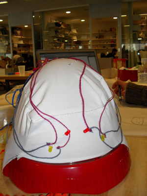
This helmet, placed on the head before bed, will allow the sleeper to wake up to light instead of a jarring sound alarm. Before going to bed, the sleeper puts on the cap and snaps in place. This snap acts as a switch, and sets the alarm system in motion. From the moment the snap is closed, a timer begins. After the programmed amount of time, lights, which have been enveloped in soft pouches over the eye sockets, begin to blink. First yellow LEDS blink, then red LEDS begin to blink, alerting the sleeper that the time has come to wake up!
Roommates love it! Bedside partners love it! You'll love it!
Design Process
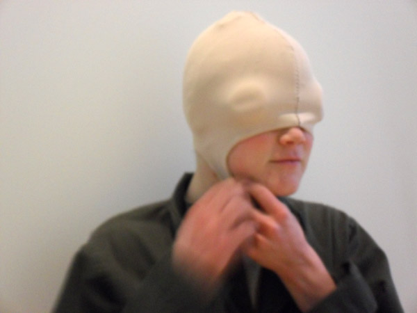
The mask was patterned to fit snuggly for added comfort during the sleeping period. Each eye pad was designed to proved a comfortable, but light sealed fit.

Technical Design
A simple state diagram helps to understand the process of waking up to your new day with this design. Waking is indicated by the removal of the helmet.

In order to accommodate the design intent of the helmet a circuit was designed composing of two yellow LEDs and two red LEDs. Each eye pad would contain one of each. The microcontroller uses the power as its indicator to begin processing the code.

The fabric PCB was designed to easily accommodate multiple ground connections and align the output signals with the physical layout of the helmet. With multiple iterations it became clear that the circular PCB typology is the most elegant way of making connector pads that are easy to interface with. The lilypad design was our obvious inspiration for the final construction.

The AVR programming for the project was fairly straight forward. Each yellow LED is lit after a given period (the amount of desired sleep time). After an initial alarm state, the yellow LEDs begin to flicker fifteen times. If the user does not wake and remove the helmet, the red lights then engage into a simultaneous flicker. This final state remains until the helmet is removed. Our final code is documented and can be found here.

Fabrication Process
After initial concept designs, we began by sketching out the fabric circuit. We then laser cut the designed circuit, then soldered the ATCmini microprocessor and protected the solder joints with epoxy.
The fabric PCB was then placed on the helmet, and sewn into place.
Problems / Future Plans
The fabric circuits, during testing and programing with the breadboard, began to disintegrate. Soldering the microprocessor to the fabric was an extremely difficult process, as the fabric burns as it reaches the temperature needed to solder is reached.
Future iterations would involve changes to the timer. For demonstrations purposes, there currently is no delay in the code. Future modifcations could easily involve changing the code, and having a longer amount of time before the alarm begins.