Main.Team5 History
Hide minor edits - Show changes to markup
the spider in action: http://www.youtube.com/watch?v=yYgol1MbuJs
By Edwina, Sara, Amy & James
By Edwina, Sarah, Amy & James
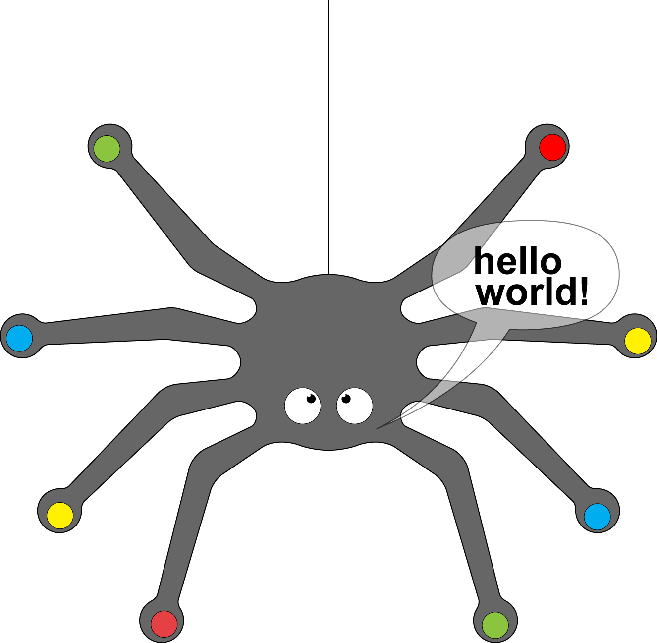
This program allows for two of the legs to turn the LED on or off. If two legs are turned on in combination the eyes will flash faster or slower. With no input the spider flashes its eyes continuously, scheming.
b1Input();
b2Input();
b3Input();
b4Input();
b1High();
b2High();
b3High();
b4High();
for(;;)
b1Input(); b2Input(); b3Input(); b4Input();
b1High(); b2High(); b3High(); b4High();
for(;;)
if (b1IsLow()&b3IsLow())
{
b0High();
_delay_ms(500);
b0Low();
_delay_ms(500);
      if (b1IsLow()&b3IsLow())
      {
         b0High();
        _delay_ms(500);
        b0Low();
        _delay_ms(500);
      }

      else if (b2IsLow()&b1IsLow())
      {
       b0High();
       _delay_ms(2000);
       b0Low();
       _delay_ms(2000);
       }
     else if (b1IsLow())
     {
     b0High();
      }
     else if (b2IsLow())
     {
      b0Low();
      }
     else
     {
      b0High();
     _delay_ms(1000);
      b0Low();
     _delay_ms(1000);
      }
else if (b2IsLow()&b1IsLow())
{
{
b0High();
_delay_ms(2000);
b0Low();
_delay_ms(2000);
}
}
else if (b1IsLow())
{
b0High();
}
else if (b2IsLow())
{
b0Low();
}
else
{
b0High();
_delay_ms(1000);
b0Low();
_delay_ms(1000);
}
}
The other issue is that we had mistakenly thought that the microcontroller could hold the input pins low instead of high. It turns out that this is not the case. As a result, the input pins would not reliably sense when the switch was open rather than closed. To solve this problem, we changed the circuit pictued above on the fly.
The other issue is that we had mistakenly thought that the microcontroller could hold the input pins low instead of high. It turns out that this is not the case. As a result, the input pins would not reliably sense when the switch was open rather than closed. To solve this problem, we changed the circuit pictured above on the fly. Instead of having the legs be tied to VCC we broke the connection and rerouted them to ground. We then changed the program to sense when the pins were low rather than high.
This is our current code: /*********************************************
 * Author: Leah Buechley

 * Filename: blink.c

 * Chip: ATtiny13

 */
- define F_CPU 1000000
- include <avr/io.h>
- include <util/delay.h>
- include "../leah_library/pin_macros.h"
int main (void)
{
b0Output();
b1Input();
b2Input();
b3Input();
b4Input();
b1High();
b2High();
b3High();
b4High();
for(;;)
{
if (b1IsLow()&b3IsLow())
{
b0High();
_delay_ms(500);
b0Low();
_delay_ms(500);
}
else if (b2IsLow()&b1IsLow())
{
{
b0High();
_delay_ms(2000);
b0Low();
_delay_ms(2000);
}
}
else if (b1IsLow())
{
b0High();
}
else if (b2IsLow())
{
b0Low();
}
else
{
b0High();
_delay_ms(1000);
b0Low();
_delay_ms(1000);
}
}
return 0;
}
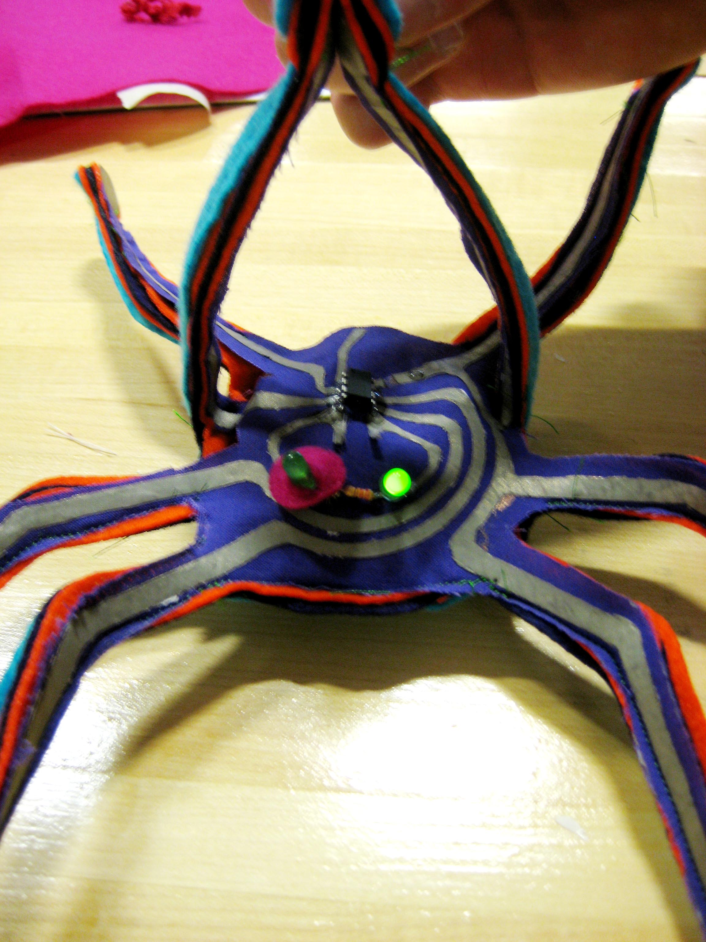
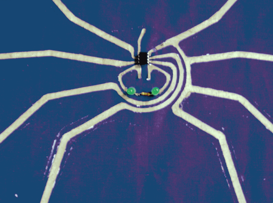
When we began programming our spider we found that there were two issues that we had not anticipated. One is that our programming configuration was a little bit awkward as we can see in the picture below:
We needed to hold some of the clips in place to ensure that we had a good connection to the microcrontroller.
The other issue is that we had mistakenly thought that the microcontroller could hold the input pins low instead of high. It turns out that this is not the case. As a result, the input pins would not reliably sense when the switch was open rather than closed. To solve this problem, we changed the circuit pictued above on the fly.
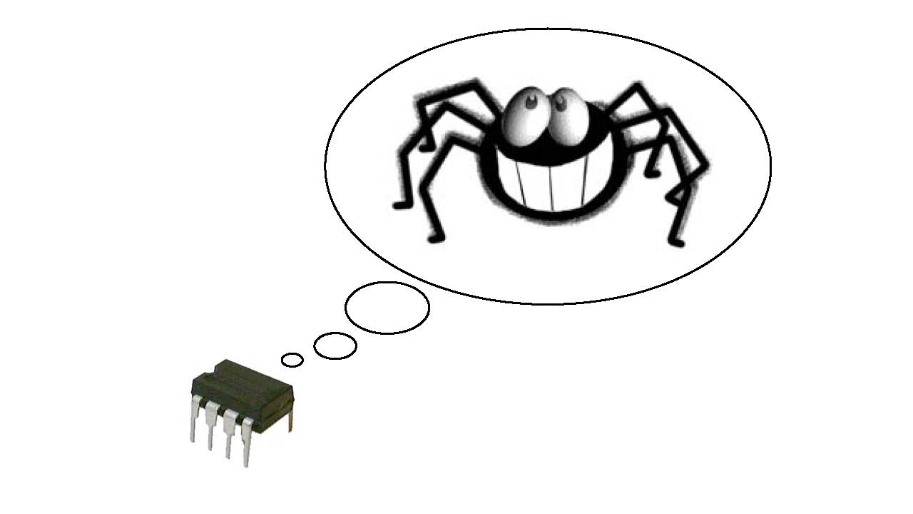
+Tiny AT's Dream \\
Tiny AT's Dream \\
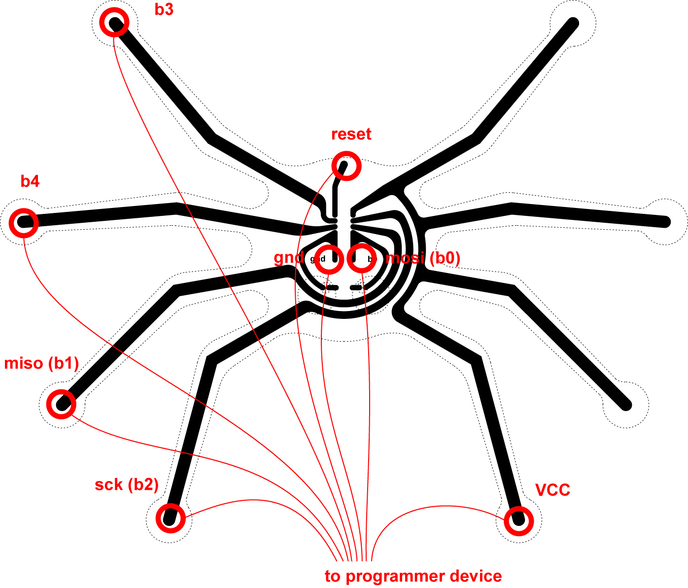
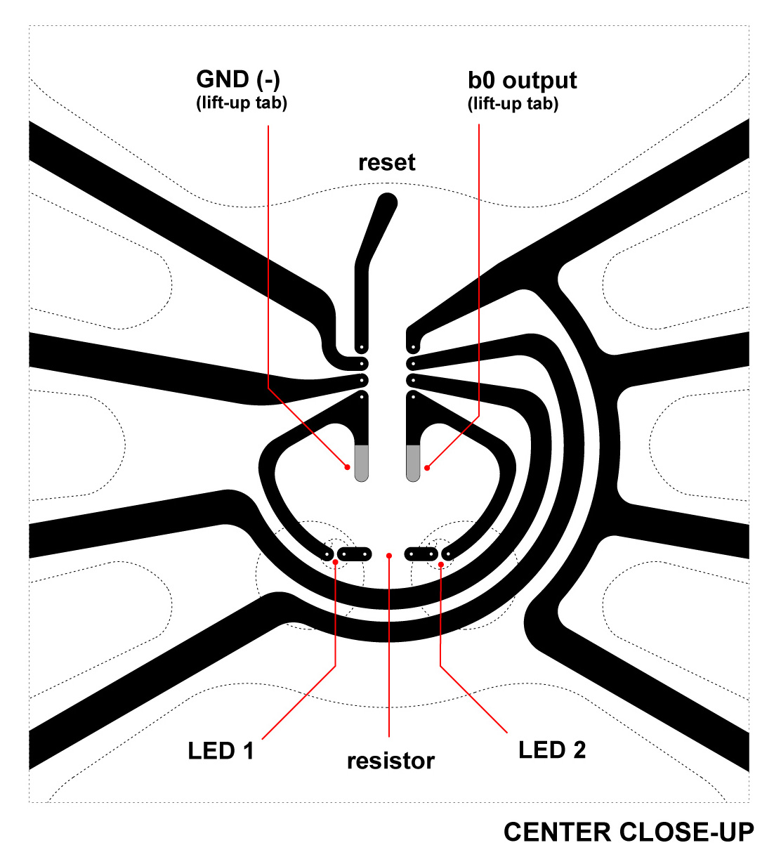
Tabs were made for GND and b0(output) because they were in the interior of the body, so the alligator clips could be attached for programming.
Programming attached layout
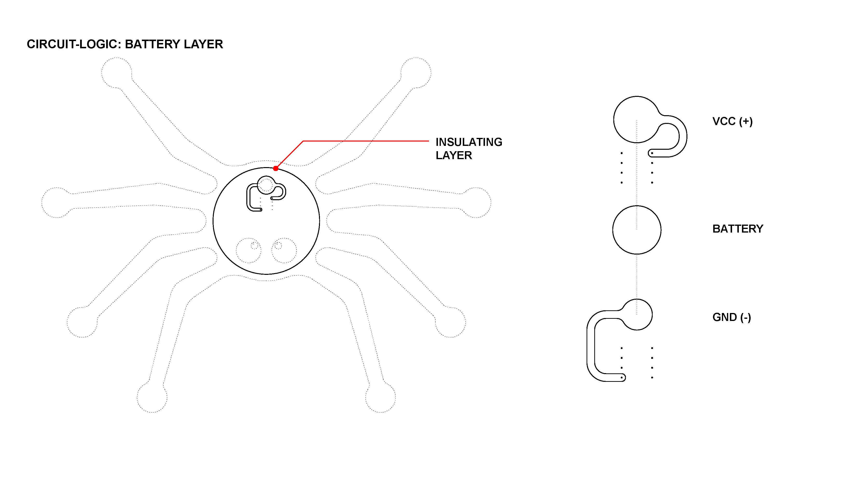
The battery layer needed to be on a separate layer. Two pieces of fabric sandwiched the battery, with an insulating layer separating it from the main circuitry layer.
\\
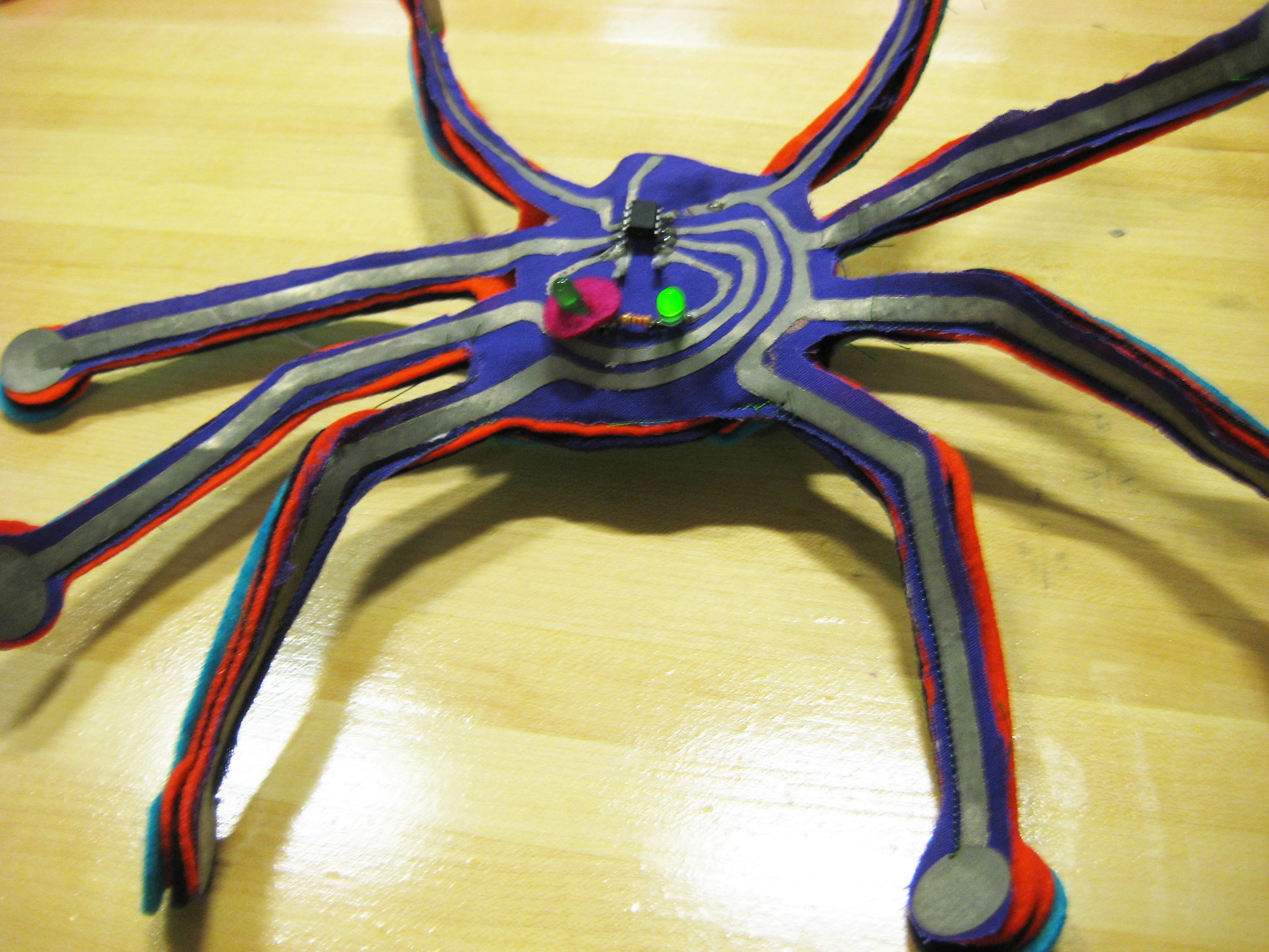
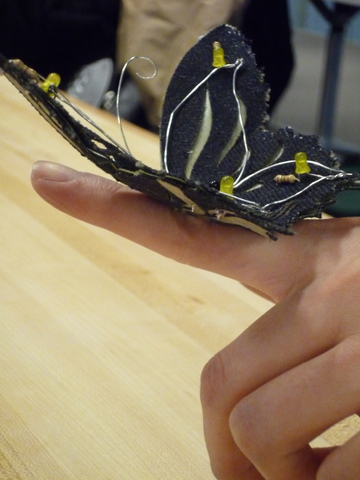
Aww, isn't he cute?
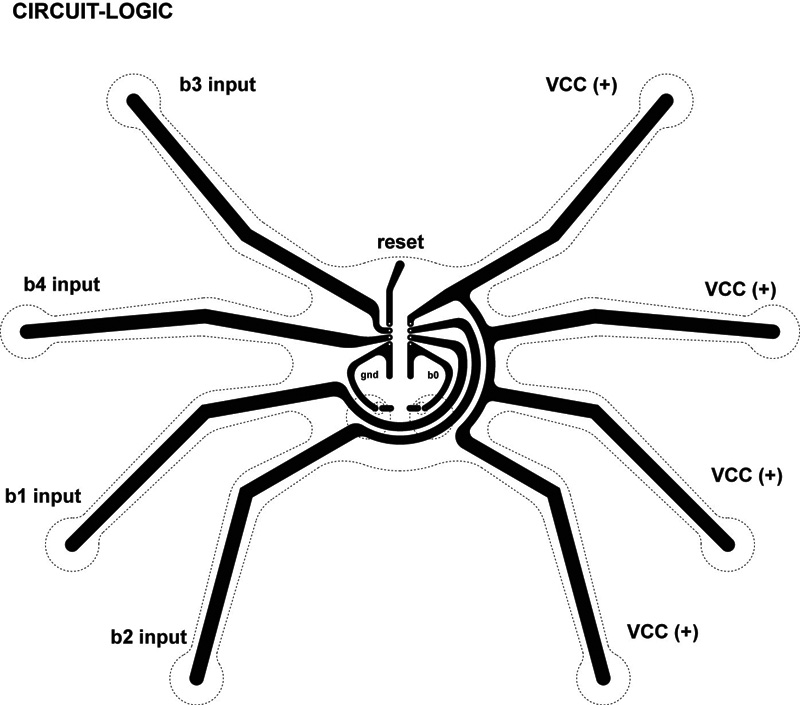
The challenge of the circuit layout was to somehow extend functionality to all of the spider legs. We decided on a scheme that would extend VCC(+) to all of the legs on one side of the spider, and b1, b2, b3, and b4 to the otherside as inputs. When any of the b* inputs come into contact with the VCC legs, that b* input would go to the 'high()' state. This way we can program multiple possible outputs (LED flashing patterns) based on the conditions of legs.
Design
Design\\
The initial idea came from a desire to extend the ATtiny13's pins outwards so they can begin interacting with eachother.
The initial idea came from a desire to extend the ATtiny13's pins outwards so they can begin interacting with eachother. The design evolved into a plush toy spider; its legs act as interactive element, and upon coming into contact with its other legs (in several different configurations), the spider's LED eyes would respond differently - perhaps to indicate its current mood. (A more complex iteration could involve coloring each leg a different color, and touching legs of different colors would generate the mixed color result, which could show up on a multicolored LED, as a way to teach a child the color wheel)
<<<<<<< Laser cutting the spider circuit proved to be trickier than we expected. We accidentally laser cut the fabric with the conductive side up, and iron-on paper down, and realized later that the paper didn't get cut. We were able to use an exacto knife to cut the rest of the spider, so we didn't need to cut another one.
=======
>>>>>>>
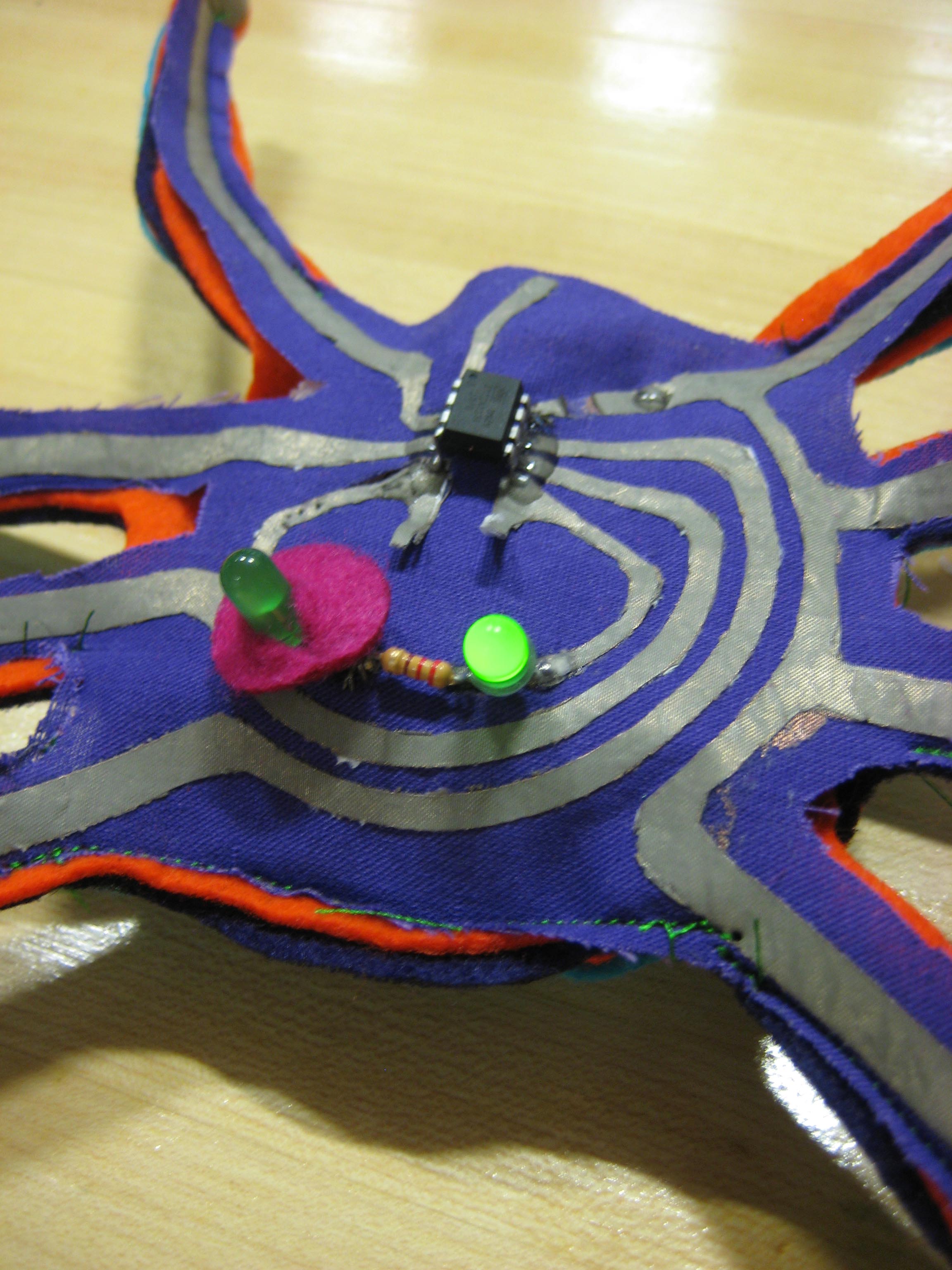
We also experienced some unforeseen difficulties with the assembly. The first was figuring out how to iron the circuit onto the backing fabric without accidentally sticking all of the legs together. We ended up taping over the conductive side before tearing away the paper, which worked very well. Once everything was ironed we soldered the components together. Because the legs of the microcontroller are so close together, we were worried that we might accidentally connect them with solder, but using very thin solder worked well to prevent this. We decided to put in two LEDs for eyes, which was not a good idea, in hindsight. When connected to the computer's power source, both LEDs (wired in series) could light up, but later when we attached the battery, we realized that 3V is not enough to light up both. However, the battery was enough to power one LED, so we decided just to short the second LED and paint it red. (No wait, that was the plan all along...)
Another thing we discovered is that too much soldering can burn the conductive fabric and cause it to tear. After re-soldering the connections multiple times, we finally decided to epoxy everything on both sides of the circuit.
The Concept
The Concept
The initial idea came from a desire to extend the ATtiny13's pins outwards so they can begin interacting with eachother.


+Tiny AT's Dream
+Tiny AT's Dream \\
Concept
The Concept
Design
Fabrication Pt I - Laser Cutting
Fabrication Pt II - Assembly
Programming
Result
Issues
+Tiny AT's Dream
+Tiny AT's Dream By Edwina, Sara, Amy & James
Concept
+Tiny AT's Dream