PCB Puzzle
by Sheralyn Woon
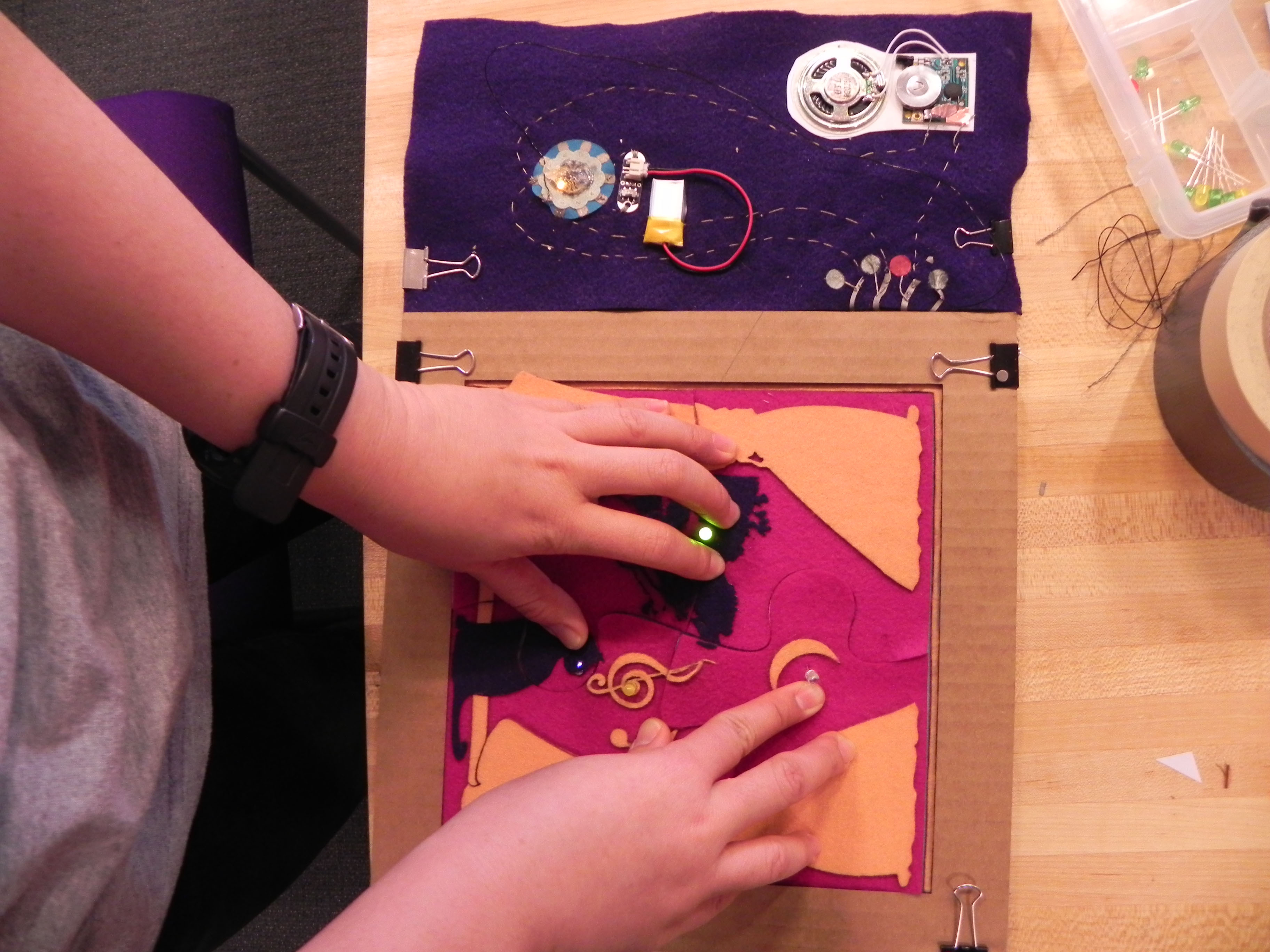
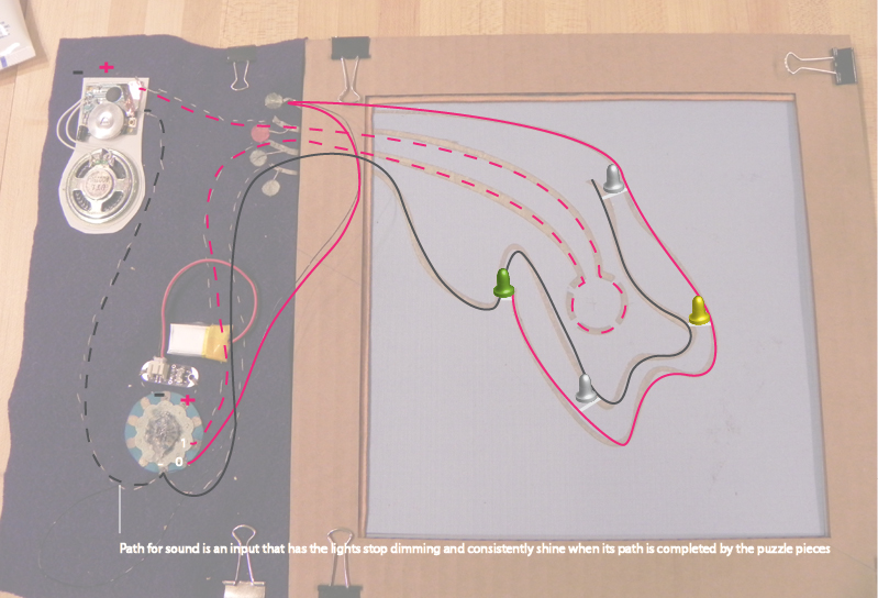
For this project, Crystal and I made a multimedia jigsaw puzzle. We used the PCB we made in class to control the interactivity between the conductive elements in our puzzle. There is 1 circuit with 2 paths: one for the light in the puzzle and one for the sound.
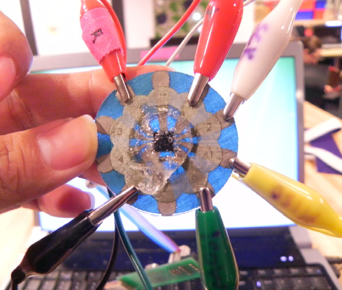
- Testing our PCB
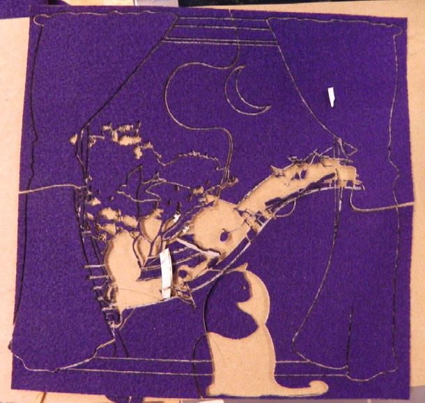
- First Experiment with Laser Cutter
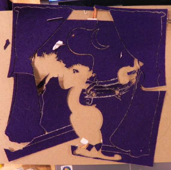
- Experiment 2 (There are fewer pieces becuase we took the photo after we ironed the pieces on the puzzle.
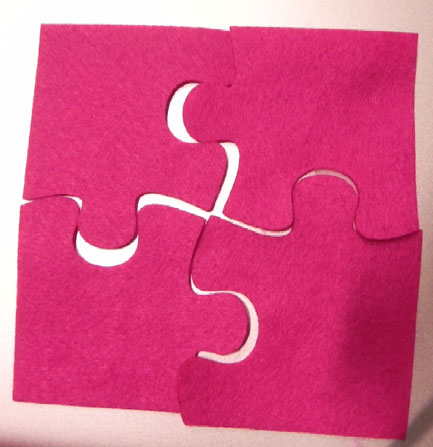
- The first cut of the puzzle… we had a problem fitting
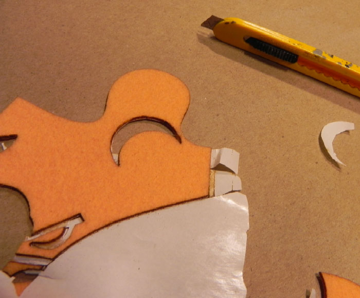
- Lasered Wool Felt
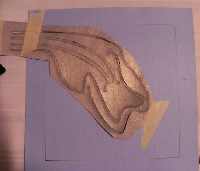
- Laser cut Circuit
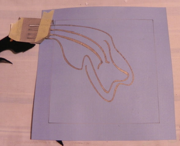
- Laser cut Circuit: Underlying circuit 2
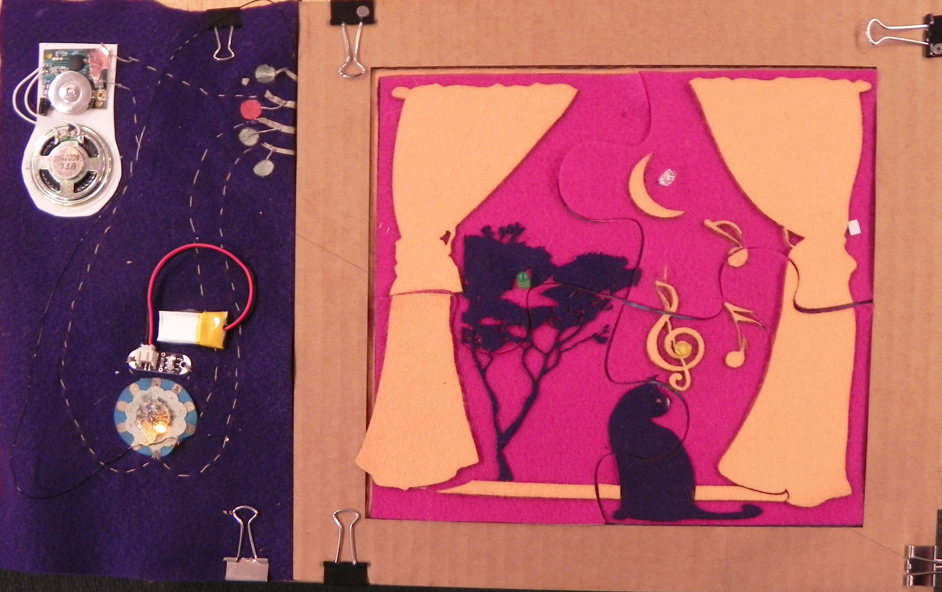
- The Final Work
- Final Circuit: Amendments to Circuit
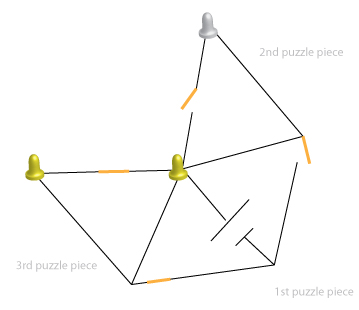
- Initial Circuit Plan
Initial Circuit
An initial circuitry design featured the circuitry inside the puzzle pieces. This design had three lights and one puzzle piece that contained both an LED and a battery. Ideally, this puzzle piece would be placed first followed by the second or third whose LED would subsequently light up if attached correctly. The order of the 2nd and 3rd puzzle pieces did not matter. If all three pieces were correctly attached, all three lights would light up. There are flaws to this design however — for example, the pieces without the batteries might be placed first and despite being correctly positioned, they would not light up because the battery was contained in another puzzle piece. After speaking with Leah, we were advised to consider how we might integrate Arduino into our circuit. We also needed to consider a design that excluded the battery and micro-controller from the puzzle pieces.
Final Circuit
In considering Arduino, we thought that perhaps we could have a pin dedicated to each LED along with an input pushbutton that kept track of whether or not the puzzle piece was correctly attached. To do this circuit, however, we would’ve needed at least 8 pins which was more than the lilypad we made in class contained. So, we simplified our circuit design and integrated a sound feature.
The path for light is triggered: When the correct piece of the puzzle is placed in place, the light on the piece will fade in and out. When all the pieces placed correctly, the light emitted will be constant.
The path for the sound is triggered: When all the pieces are placed correctly, the “Celebration” song is played.
The code for the PCB is:
int brightness = 0; // how bright the LED is
int fadeAmount = 5; // how many points to fade the LED by
const int buttonPin = 1;
int buttonState = 0;
void setup() {
//Initialize the PINS
pinMode(0, OUTPUT); // ALL on , FADING each will start fading when put in the correct spot
pinMode(buttonPin, INPUT); // Pushbutton, when all are assembled correctly, they complete a circuit which turns on the music
// When the music turns on/circuit is completed, the lights stay on, NO FADING.
digitalWrite(buttonPin, HIGH);
}
void loop() {
buttonState = digitalRead(buttonPin);
// check if the pushbutton is pressed.
if (buttonState == LOW) {
analogWrite(0, 255); // all turn on to brightness.
}
else {
analogWrite(0, brightness); // all turn on to brightness.
brightness = brightness + fadeAmount;
if (brightness == 0 || brightness == 255) {
fadeAmount = -fadeAmount ;
}
// wait for 30 milliseconds to see the dimming effect
delay(30);
These are our videos
Learning Points:
1. Use similar LEDs for parallel circuits to ensure that all light up at the same time.
2. Use magnetic or conductive velcro attachments to complete circuits.
3. Measure the resistance of the circuits to ensure batteries are not overloaded.
4. Create another separate circuit for the sound so that it doesn’t go through the micro-controller.
