PCB LED Cell Phone Case
by N.Tari
By Nicole and Heidi
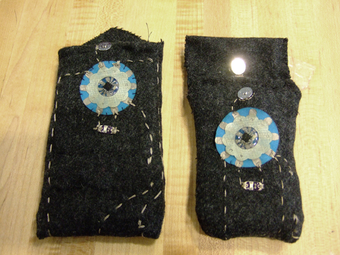
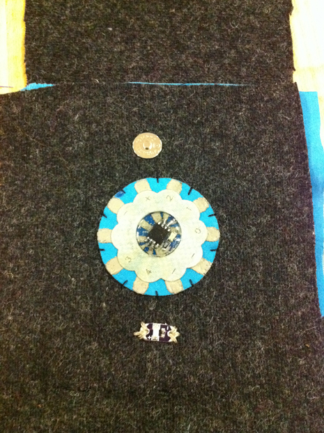
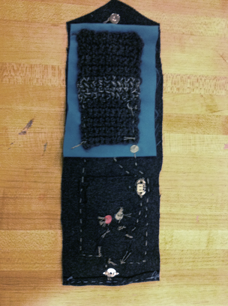
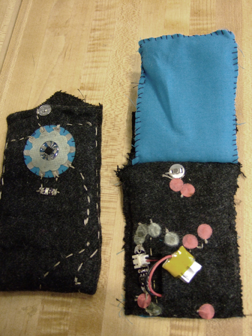
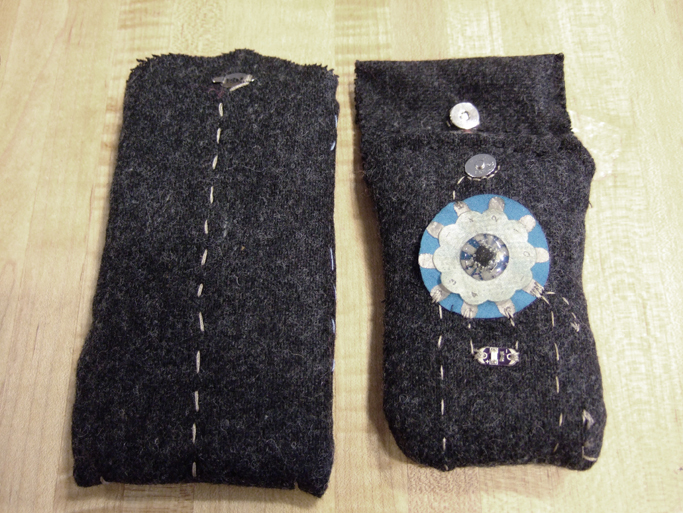
At the start, we decided that we wanted to build a prototype that uses pressure sensors to trigger some reaction. With this in mind, we designed a cell phone case that would alert the user to a missed call or text with LEDs. When the phone vibrates, the felt case dampers the sound of the vibration and simultaneously triggers a blue LED to signal an incoming call/text. The program in the PCB turns on a fading yellow LED that keeps fading on and off until the case is opened, so that the user is constantly reminded of the missed call or new text message. This would allow the user to keep track of their cell phone even in a quiet environment like a library, as it converts auditory feedback into visual feedback.
Process and Technical Problems:
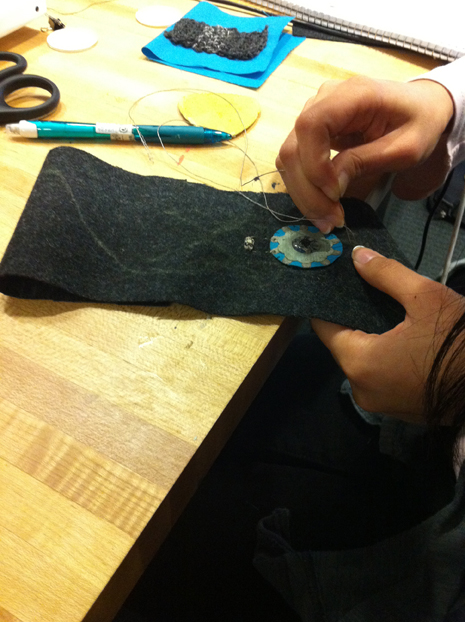
We both learned a lot in doing this project, from building fabric PCBs and textile sensors to figuring out how to use them in an integrated textile circuit. As part of the learning process, we made a phone case each, which was nice because our phones are not the same size.
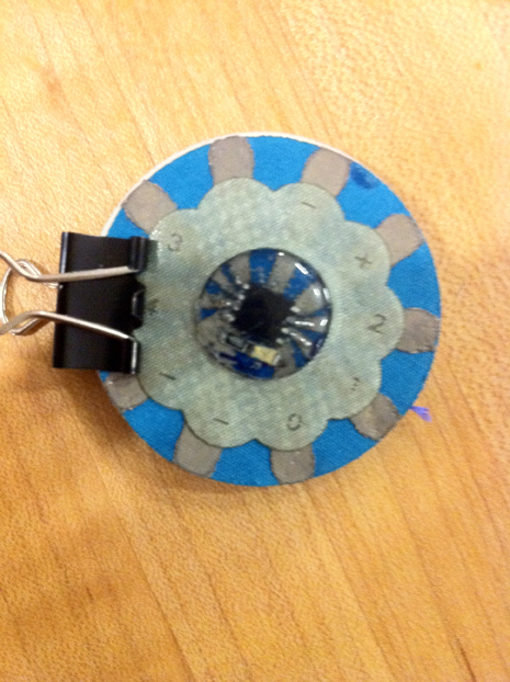
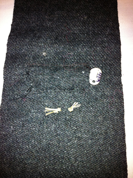
We ran into problems early on in the project, with our AtTiny85 chip losing contact with the conductive fabric base several times . On one PCB, we resorted to burning a hole through the back of the fabric in order to solder the contact close. Programming was also tricky as we discovered that we were shorting out the PCB as our components were connected to the pins 1 and 2.
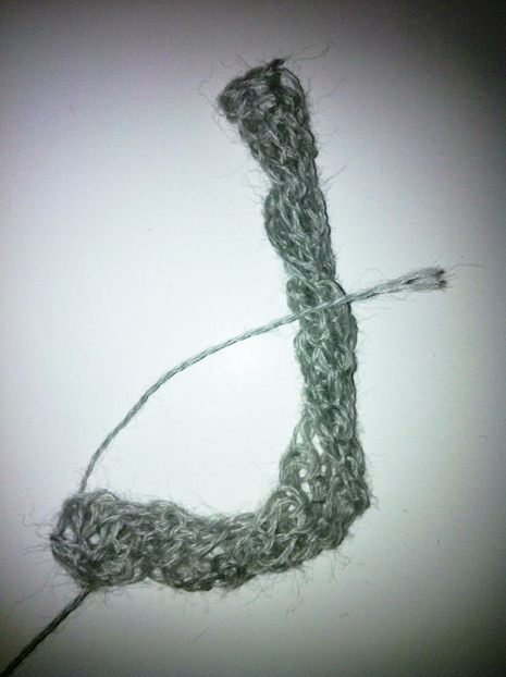
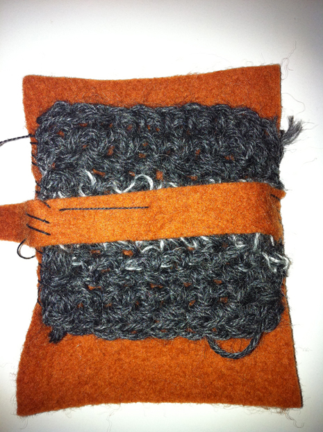
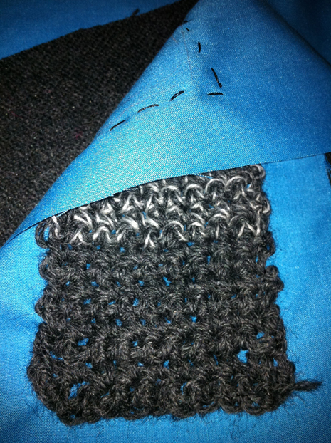
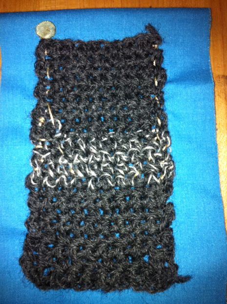
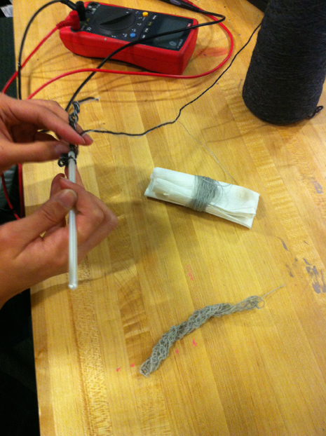
Inspired by Hannah’s sensor examples, we experimented with several crochet pressure sensors to pick up the vibrations of the phone. We went though many different sized sensors before settling on the one inside the case. The sensor is constructed of crocheted yarn in a patch the size of the phone. In the middle is a strip of conductive yarn mixed with wool yarn. There are positive and negative threads running though the sides of the sensor that are connected to the PCB to trigger the LEDs. Pressure on the conductive patch of the sensor would decrease the resistance of the path and hence make the signal at the PCB stronger. We used trial and error to “calibrate” the sensor. Before we resorted to trial and error, we made an attempt to draw data from the sensor. Quickly after starting we found that Println(); cannot be used with the AtTiny85 because it does not have the same hardware as the Arduino. Leah helped us with the software serial library in hope that it would allow for data to be read. Unfortunately we could not make the speeds of the PCB and computer sync up and were not able to draw usable data.
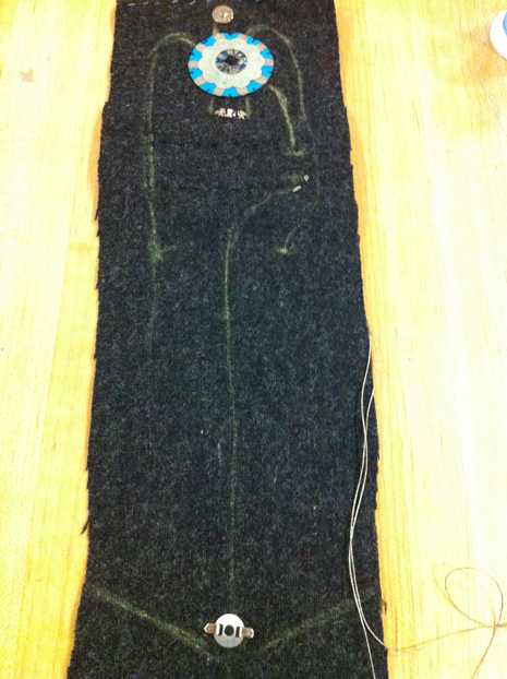
Eventually, the sensor functioned in the way we intended and we started to map out the circuity and design the case. Once everything was sewed together we needed to re calibrate the sensor. This is when things became tricky and the sensor finicky. Proof of concept has been achieved but currently the case is unreliable. We think that because the sensor is woven after some time the sensitivity changes because the fibers vibrate into a position that is not a sensitive and is more stretched out. Some of the unreliability may also be caused by the changes in voltage as the battery slowly loses it charge. However, the circuit still works when the case is squeezed. In the future, we will consider using a sensor that is more suited to sensing vibrations, like a piezoelectric sensor, instead of a simple pressure sensor. However, we still think that the project was a success as we learned a lot from the process of making it.
Images:
To view us testing the sensors click here: http://www.youtube.com/watch?v=YtR3RHIZZE8
Here is a video of the case working before sewed together http://www.youtube.com/watch?v=_ZHjxvbGjWA
Here is the final working product:
Here is the final working differently than intended:
Code:
