Twist Switch
by lmctague
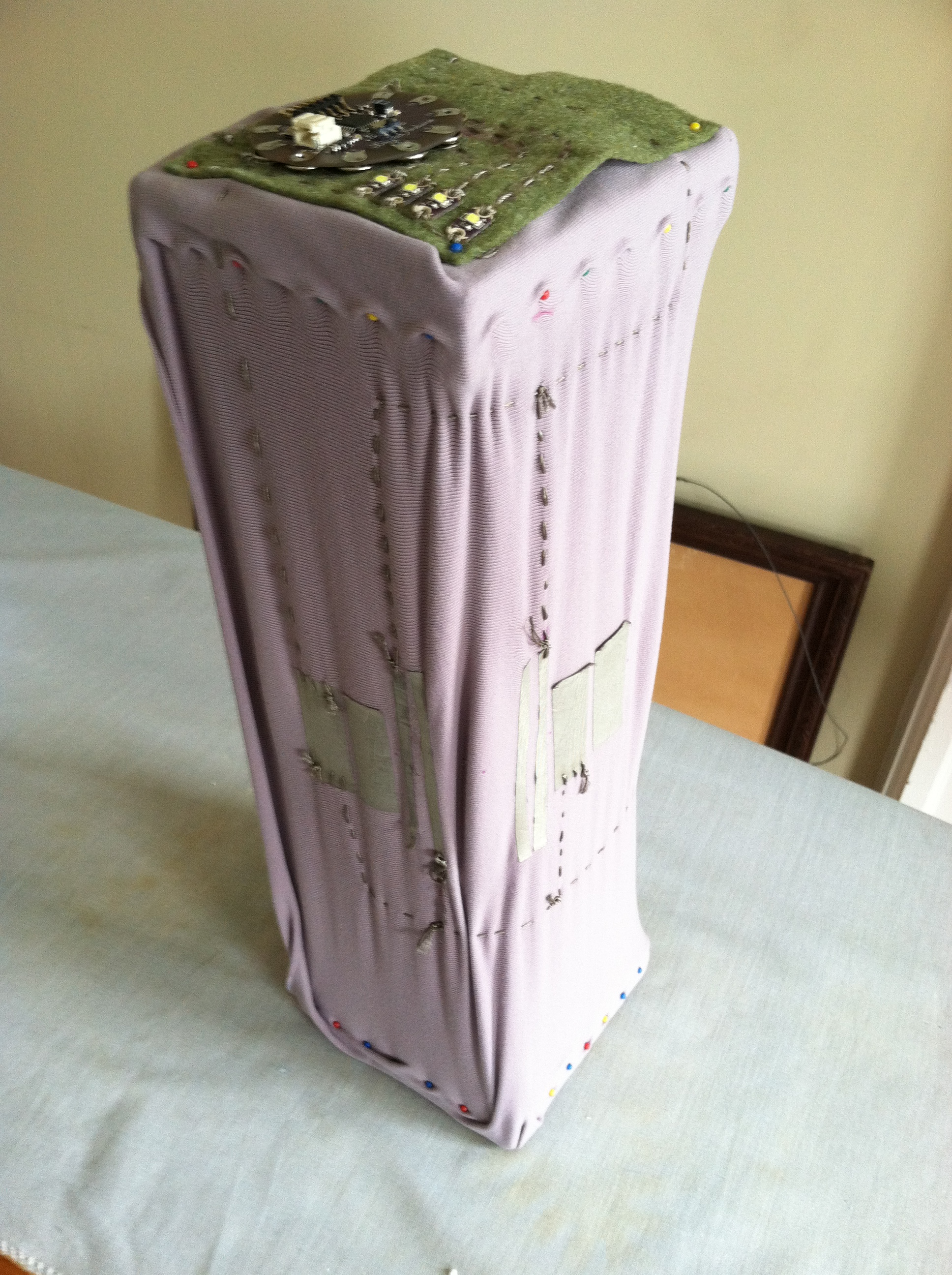
Through the action of twisting, swatches of conductive fabric are folded in upon each other, completing a circuit that then turns on LEDs.
On each face of stretched spandex are swatches of conductive fabric. Before choosing which swatches to designate as either + or -, I tested the twisting motion to identify which swatches were coming into contact. Some clearly were never going to touch, while others made contact when twisted in one direction while failing to connect when twisted the other way.
The four faces are divided into 3 sensors. The following diagram maps out the routes of the positive and negative currents and how they hook up to the input / output pins on the Lilypad arduino.
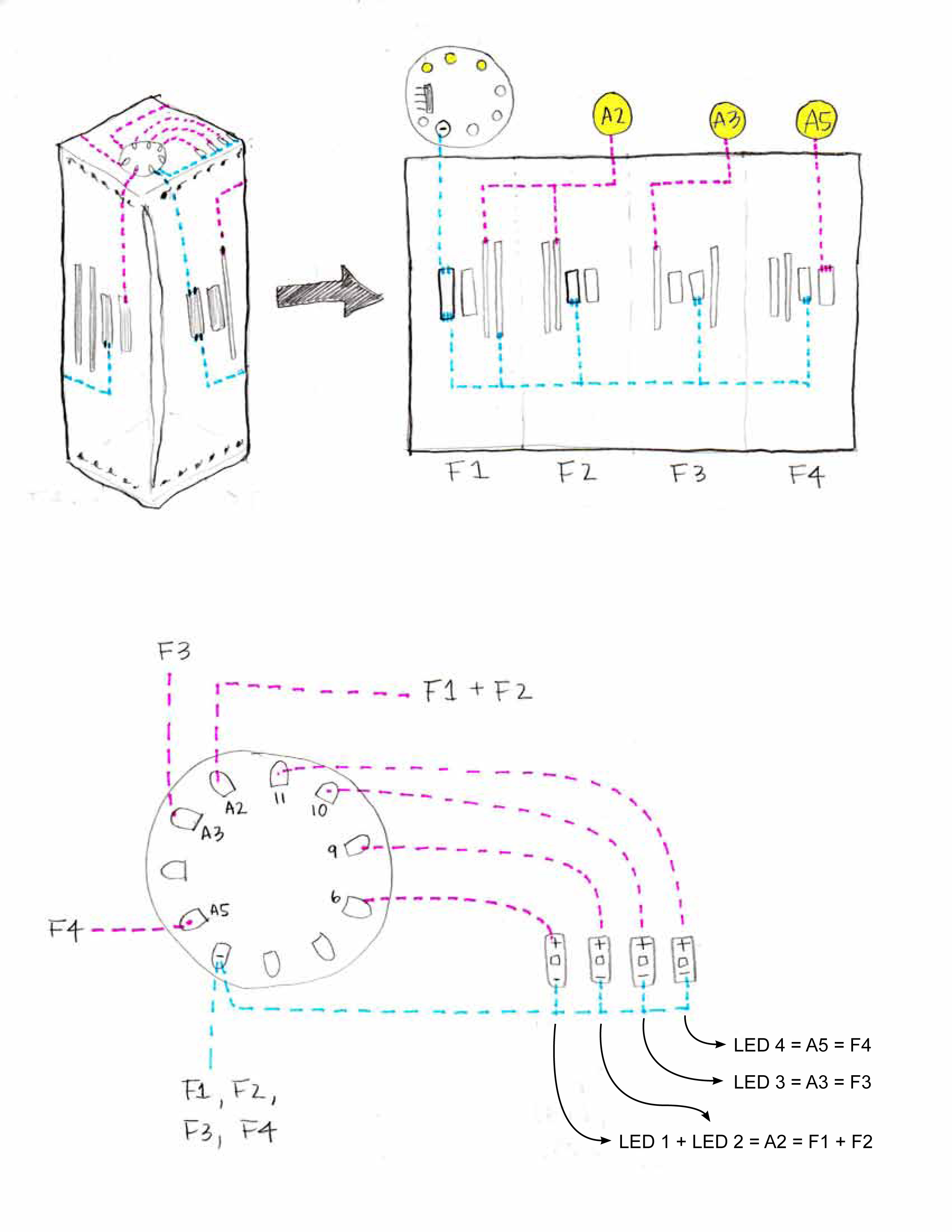
Faces 1 + 2 (F1 + F2) share a positive circuit which together go into input A2.
Likewise, F3 goes into A3 and F4 goes into A5.

The resistances for each of the sensors share a similar range: approx. 1000 ohms when at rest and 16 ohms when touching. Therefore, the voltages range from 4.86volts when at rest to 4.99volts when activated (nearly the full 5volts of power that comes from my computer).
The arduino code was written such that when the piece is twisted (and the resistances dip below 600 ohms), LED 1 + LED 2 turn on. Similarly, LED 3 and LED 4 also turn on, but blink … with LED 3 blinking twice as fast as LED 4.
What I find interesting about this particular project is the variability of the twisting motion. Whereas the spandex does seem to fold in similar fashion every time, it isn’t reliably consistent. Not only that, but a twist to the right does not produce the same results as a twist to the left. As such, the sensor then becomes the means by which to test whether certain areas of a stretched fabric are coming into contact when twisted. And by locating sensors in several places across the surface, you can obtain separate readings for each of the areas / sensors by programming a different LED response.
Here is the code written with Emily’s excellent help (yay!):