On last Tuesday’s presentation class I was very impressed by the magnetic, flexible silicone that Leah has showed us. For this assignment response I wanted to experiment with magnets and make a soft material that could attract them. I used a steel fiber and mixed it with Angelina heat bondable fiber.
For this project I experimented with computerized plotting on T-shirts using Micron brand drawing pens. To date this has been the most fun thing that I’ve made on my Multifab personal fabricator . I’m starting to think that fashion might be the under-explored killer app for personal fabrication.
I wanted to write a program that would generate different faces. I have started with the “tree” source code that Leah has provide for the embroidery machine toutorial. I was changing the properties untill I found the result close enough my idea. I picked up three random face-bases and I added the eyes in Adobe Illustrator.
I used the Angelica Fibers and ironed them together. I found that a 3D soft object with no seam can be created just by ironing carefully. When the fibers are mixed together, the sheen is very metallic.
I then sandwiched the paper-like substance between two sheets of the dissolvable film and ran the whole thing through the sewing machine. I sewed some random lines all the while playing with the stitch length and density. After half an hour, I ran the whole sheet under water and I got this lacy, paper-like textile.
I struggled on what to do for this project as I kept considered doing a 3D print fabric. However, I’m somewhat satisfied with my experience on the embroidery machine as it did give me some ideas on how to tackle my final project.
Through Processing, I made a (8 bit) Angel fish by using overlapping triangles. It’s a small tribute to early computer graphics.
In the embroidery software, I learned that there were 26 shades of blue. Obviously, I didn’t have 26 shades of blue embroidery thread, so I choose to combine similar colors into 5 groups…
…On the embroidery machine, however, I learned that my 5 groups weren’t 5 groups as I ended up having the option to change the color some ~15+ times.
Embroidery machine showing sections to be embroidered with thread installed on machine (for lack of better words).
In addition to not having as man groupings as I thought, I also had difficulty with tension and as a result, the bobbin thread made a random appearances and the sewing thread kept accumulating into messy tangles
Initial embroidery completed until I changed the bobbin
Tension on the new bobbin is too tight...
...bobbin tension still too tight...
Snag
Final Result
Following another student’s example, I decided to switch to a thicker fabric. The final embroidery still has the bobbin thread showing, but I suppose that this project was an experiment as I did switch threads several times and as a result, found by trial and error different tension settings for the threads as the automatic tension setting didn’t diminish the appearance of the bobbin thread.
Some things I learned and that I should keep in mind for my final project:
I should use a bobbin thread whose color is close to the fabric, which is something that’s similarly done in quilting.
I also learned that for embroidery that has adjacent different colored sections, it’s NOT a good idea to cut the thread when the machine gives the option because as I learned at the very end, previous embroidery can become undone.
Pre-test the tension settings for the thread and fabric I plan to use.
Angle Fish
Code:
int x=0;
int y=0;
int a=50;
int b=0;
int e=0;
int f=50;
I have always been interested in patterns that were capable of change. For my Computational Design Project, I chose to design a circular pattern that could deform in shape and size. Using Grasshopper, which is a plug-in for Rhino, I used pre-determined values and a code to generate a 3 dimensional cylinder that expands and contracts at its center. I then used the top views of the cylinder’s deformed surface to capture different radial shapes for laser cutting and embroidery design.
Grasshopper plug-in with Slider to adjust radial shapes
Shapes generated by moving the slider
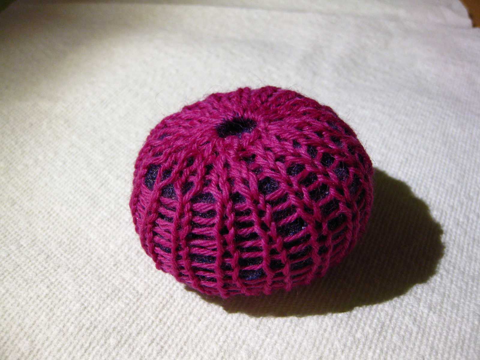
Below is an image of one of the shapes imported into Ilustrator as a 2 dimensional vector file for use on the laser cutter and embroidery machines. When I imported the file, many layers of lines were produced as a result of the 2d image being a projection of a 3d object. I had to delete any duplicate lines in order to prevent the laser cutter from over etching a single line, and to prevent the embroidery program from crashing. Over etching in areas did produce some nice results as well however. The darkest lines seen in the design below (creating a circle) were over etched and caused the center circle to fall away from the etched border. This allowed me to mix and match different patterned/colored circles for the center of the design.
Once imported into the laser cutting program, I used felt as the base for the design to be etched onto.
Various shapes were pieced together with a fabric adhesive
Finished laser etched designs
Embroidery
Finished embroidery
Rhino/Grasshopper C# code
private void RunScript(OnCurve c1, OnCurve c2, On3dPoint pt, double dd, ref object A, ref object B)
Make a piece of flexible nonwoven fabric with some noteworthy characteristic. (An unusual blend of materials, interesting structural characteristics, embedded circuitry, special electrical properties, …?) Create a post that documents your project and add it to the Nonwoven category. Your page should include a photo of the finished nonwoven and a short description of the fabric and how it was built. Since you are also working on your final projects I am not expecting you to spend as much time as usual on this assignment or its documentation, but I wanted you to get a chance to play with some of these materials and techniques. A single photo and a few sentences is fine.
For this computational textile assignment I want to try the 3D printing textile. It is a good experience of learning!
It is my first time to do 3D printing, and I am a new hand in Grasshopper. So the work is challenging. I started from studying the basic structure of weaving, and then tried my best to build it in Grasshopper in Rhino, and managed to make a structure similiar to the textile weaving. The basic method is to build U-V grids on both sides of a surface, connected the points by nurbs, flattened them and deleted some points by “cull”, and finally “pipe” the curves.
After spending long time on learning the software and building the model, I could not catch up the deadline to send the file to shapeways. So I went to the Edgerton Student Center for 3D printing. However, since I do not have enough 3D printing experience, I did not “cap” the ends of pipes and the model printing totally failed.
Then I rebuilt the model and printed it again, which took an terrible long time of 24 hours…
Finally I got the model printed. However, the result is not ideal. Several parts are broken. Before going there, I did not know that there are many kinds of 3D printing and each has different characteristics. The 3D printer in Edgerton is based on FDM which is when the plastic gets squirted out in a bead. I did not realize it was too low resolution for my delicate model.
It is a very interesting process of learning! I want to thank Ilan Moyer, who is an expert in mechanical techniques and helped me a lot with the 3D printing!!
The pattern that I used to generate this code was a old data set that I modified to allow the results I wanted. The data set is a text file that is read by processing though the help of tabs. I acquired the data from a questioner I sent out to friends. Read the rest of this entry »
Inspired by the rotational artwork that I used to do when I was a kid, I wanted to create curves that could be rotated about a center point to form a piece of unique art.
I focused on the motif of a button because firstly I thought it was a simple object to work with and secondly I wanted it to appear as if one was continuously pulling open a drawer with loads of buttons shifting about inside. In the first version of the program, I had problems representing this shifting motion. The buttons were actually stuck in place because I couldn’t figure out how to make the small button holes follow the big button. This is also why the rest of the smaller circles moving randomly have no button holes.
After some intensive coaching from Leah, the next few “improved” versions actually had buttons moving about. Playing about with sizes and numbers of buttons, I had a variety of densities to choose from. The final one I used has some density but does not seem overwhelmingly crowded (pictured above). I waited for the right composition and just clicked the mouse to save the image as a Tiff file.
Using the DRAWings program, I turned the tiff file into an embroidery file. I played around with the density of stitches and way the program translated the Tiff file into vector. I found that the accuracy could be adjusted for different effects. In my first piece because the accuracy wasn’t set high and the stitch density is too high, the distinct look of the buttons has changed. It looks more like a diagram in a biology book about cells and amoebas. The second piece with a lower stitch density and higher accuracy, the original look of the buttons is retained.
The sewing machine was generally ok to me. I found it very engaging to play with alternating the thread colors and getting the machine to sew over bits that had already been done to blend colors or create more texture and depth. I also tried both cotton and felt as an embroidery backing. I prefer the look of the felt because it is more robust and doesn’t pucker as much. The back and the front of my designs are of different colors because I changed the color of the thread on the bobbins to experiment with different color schemes.
I really appreciated having more time to work on this assignment, in spite of spending most of that time staring at the Programming screen wondering what I could change or rectify. Without the time I don’t think I would have been able to be really make the movement of the buttons seem random.
This is the video of the random patterns made:
The code for the final pattern is:
void setup() {
size(600,400);
frameRate(1);
}
void draw() {
background(0);
color c1 = color (255, 0, 200);
drawButton1 (50, random(width),random(height), c1);
int x=0;
while (x<8)
{
drawButton1 (int(random(80, 120)), random(width),random(height), c1);
x=x+1;
}
color d1 = color(50,0, 255);
int y=0;
while (y<30)
{
drawButton2 (int(random(40, 75)), random(width),random(height), d1);
y=y+1;
}
}
void drawButton1 (int sizeOfCircle, float centerX, float centerY, color c)
{
int bigCircleDelta= sizeOfCircle/2;
int buttonDelta = 5;
int sizeOfButton = 3;
fill(c);
ellipse ( (centerX), (centerY), sizeOfCircle, sizeOfCircle);
fill (0);
ellipse ( (centerX-buttonDelta), (centerY+buttonDelta), sizeOfButton, sizeOfButton);
ellipse ( (centerX+buttonDelta), (centerY+buttonDelta), sizeOfButton, sizeOfButton);
ellipse ( (centerX-buttonDelta), (centerY-buttonDelta), sizeOfButton, sizeOfButton);
ellipse ( (centerX+buttonDelta), (centerY-buttonDelta), sizeOfButton, sizeOfButton);
}